An examination of archaeological remains provides only a dim outline of the actual physical methods that might have been employed to smelt iron during the Viking Age. The conversion of natural ores into metallic iron, and then progressing to finished objects, is a complex set of activities. The physical evidence that can be examined directly by the modern researcher at best represents only the final minutes of a dynamic process that takes many hours to complete. Starting with forms suggested by archaeology, a small team from Ontario, under the leadership of Darrell Markewitz, has conducted over a dozen experimental iron smelts. The intent of this ongoing series is to develop practical working experience with tools and methods which approximate those available in Northern Europe during the Viking Age. This paper outlines the experiments the team has undertaken to date, the results and lessons learned, and discusses some insights that may be of interest to the larger community of researchers.
Note: This is the full text of the original paper that was submitted in
March of 2006. In January of 2009, this paper was largely re-written for publication,
and also to include all 39 experiments to the end of 2008. The 'long version'
of that text is available : Continued Adventures in Early
Iron Production
Introduction
Beginning in June of 2001, a series of experimental iron smelts have been undertaken,
a total of thirteen up to the end of 2005. The basic methodology has been established,
both in terms of physical process and record keeping. The individual smelter
designs have been on historical models suggested by the archaeology of the Viking
Age. These have then been constructed using a combination of historic and modern
materials and equipment. A consistent physical method is being established that
allows for predictable production of workable iron blooms. Next modern elements
are slowly being replaced with more historically accurate ones as the series
progresses. The intent is to gain practical experience in the overall process,
leading back to the reconstruction of a method that might
have been used during the Viking Age.
In June of 2001, Parks Canada assembled a small team at L'Anse aux Meadows NHSC
in Newfoundland. This week long project focused on iron smelting during the
Viking Age, most specifically related to the Norse occupation at that site.
The intent was to develop the interpretive methods to be used in presenting
a new reconstruction of House-site J, described as 'the Smithy' by Stine Ingstad &
Eldjarn (1). The main feature of this
structure was remains of an iron smelter. This discovery is notable as it marks
the first known production of metallic iron in North America, circa 1000 AD.
The consultants were comprised of archaeometallurgist Arne Espelund, archaeologist
Dr. Birgitta Wallace, Debbie Anderson for Parks Canada, Mark Pilgrim from the
Interpretive Staff, and myself (as Program Designer and working Blacksmith).
After an overview of the dynamics of iron smelting and the process in general
and a background of the archaeology at L'Anse aux Meadows, a simple smelter
was built and fired. Although from a practical standpoint, this test was more
remarkable for the number of things done wrong than done correctly, it did initiate
the experimental series that followed.
Another important influence on the development of these experiments was the
participation of several team members in a demonstration smelt by Lee
Sauder and Skip Williams at the Frontier Culture Museum, Staunton Virginia
in October 2002. Sauder and Williams have stressed development of a predictable
method, designing modern equipment derived from a Romano British prototype and
establishing a dependable physical sequence to conduct a successful smelt.
The primary participants in the experiments have been members of the
Dark Ages Re-Creation Company. None are trained archaeologists, historians,
or researchers, and in most cases, even as metalworkers. All the resources required
to mount each experiment have been provided directly by those involved. This
has had a definite impact by limiting the frequency of individual experiments.
It also has meant that instrumentation is extremely limited, and things like
chemical analysis are almost impossible. The team has no direct ties to any
academic institutions, so has limited access to published research by others.
All these factors have assuredly lead to much duplication of known mistakes
and also reduces the impact of any possible 'discoveries'. This is balanced
by the accumulated experience gained from many hours hunched over bellows and
feeding charcoal into smelters.
Experimental Overview
Appendix A is a simple overview of the main features
of the thirteen experimental smelts undertaken up to the end of 2005.
Notes on the Overview :
1) The furnace types listed in the Overview are described under 'Primary Smelter
Types'' below. From reading other authors (Pleiner), it is clear that
there is an established typography. That sequence however is more detailed than
required to differentiate the various furnace types described here.
2) The measurements on ore and charcoal are determined by the use of specific
pieces of equipment. There is a standardized 'scoop' for ore, which holds 335
gms (3/4 lb) of rock or 450 gms (1 lb) of taconite ore. Charcoal is added by
a 'bucket', which holds roughly 2 kg (5 lbs). Additions are recorded by scoop
or bucket numbers, then totals derived mathematically.
3) Individual experiments are listed by a number in the upper right of each
description. The first number is the overall sequence, a second number after
D indicates the sequence of DARC team smelts.
Those wishing to see the detailed notes and photographs recording the sequence
of any individual experiment are referred to the web based documentation at:
www.darkcompany.ca/iron
General Note on Materials
Through an observation of various smelters and furnace constructions, there
is a relationship between smelter height, charcoal particle size and ore
particle size. There is also an observed relationship between the ore type,
ore iron content and smelter wall material on the amount and quality of the
slag produced. Slag management itself has proved critical to the formation of
a compact bloom, and to controlling the final carbon content of the metal within.
The pioneering work of Sauder and Williams has established many of the basic
principles and working methods upon which the details under consideration here
are based. ( 2 ) .
Ores:
Regardless of the type of ore used, the ideal particle size for the scale of
smelters used in this series has been found to be that ranging from 'pea to
rice', retaining any dust produced in the crushing process. This gives a range
of 10 - 2 mm for the bulk of the ore added to the smelter, sized by eye.
In almost all cases, the raw ores have been roasted as the first step in their
preparation. This converts the FeOOH (geothite), as deposited, into the magnetic
form Fe2O3 (hematite). When using primary bog ore, considering the porous nature
of this material, it also removes the water, and also any organic materials
still present.
A number of methods have been used to heat the various ores, primarily based
on ease of handling. The bog ores used, because of their small particle size
(roughly 5 - 10 mm), were heated to a dull orange (roughly 750 C) on a open
pan inside a propane gas forge. These were then air cooled.
When working with the Virginia rock ore, an attempt is made to select pieces
when gathering at the mine that experience indicates by their colour and texture
have higher iron content. Ideally pieces roughly fist sized or slightly larger
have been chosen for ease of handling.
Two methods have been used to roast these larger pieces. For the material used
for smelts 3 through 6 plus number 13, a hardwood fire had been built in a shallow
trench. The ore was placed in the middle and the fire burned down to ash. Once
cooled, the fragments were gathered and reduced through hammering to the desired
particle size. A 1/2 inch (about 12 mm) mesh was used to sort out any larger
pieces for further reduction.
For smelts 7, 8 and 12 the ore was heated in a large propane gas forge. It was
discovered by L. Sauder during the workshop session in February 2005 that quenching
directly from the furnace served to shatter the pieces. They absorbed no noticeable
water, but proved much easier to break down under the hammer to the required
particle sizes.
The prepared taconite did not require roasting for chemical conversion, having
already been converted to the hematite form during its preparation. The roughly
20 mm spheres proved very difficult to shatter to the smaller particle sizes
required. In then end these were also heated in the gas forge on a open pan.
Quenching these was found to greatly ease this process. On smelt 13, mainly
due to time constraints, the pellets were smashed without quenching. This did
not appear to have any effect on the progress of that smelt.
Primary Bog Ore
There is considerable confusion among the current generation of North American
iron smelt enthusiasts about exactly which material the term 'bog iron ore'
refers to. The term has come to describe materials with a wide range of physical
and chemical properties, and seems to be applied regionally to describe any
iron rich material, not obviously a rock ore, that is found in lumps near water.
The term 'primary bog ore' is therefore proposed to describe a geothite (FeOOH)
material which:
- is newly formed
- is a product of the chain of iron rich bedrock, leached by tannic acid bog
water then deposited via the action of bacteria along the margins of small streams
immediately below the source bog.
For the initial test smelt at L'Anse aux Meadows in 2001, Dr. Wallace had provided
a small amount of primary bog ore (about 2 kg). This material had been gathered
during her excavations of the site in 1974. Black Duck Brook flows down through
the Norse occupation area, a few feet from the remains of the original furnace
hut. When the Norse lifted the peat turf blocks to construct the long houses
that define the site, these same nodules of bog ore would have been exposed.
Samples of the material used for the first smelt test were later analyzed (3)
and found to be extremely high in iron oxide, with a Fe2O3 content of roughly
90%.
Armed with knowledge on how to spot likely primary bog ore locations gained
from A. Espelund, several afternoons were spent hunting the margins of area
brooks, outside the protected Parks Canada boundaries. At a spot close to St.
Lunaire (about 15 km south of L'Anse aux Meadows) a good deposit was discovered.
In about a hour roughly 22 litres of wet ore was gathered. This material would
be used as the primary charge for experiment 2. A sample of this material was
later analyzed (4) and found to average about 65% Fe2O3.
What has been described as 'bog ore' has been utilized for small scale commercial
productions historically at a number of locations across Ontario. An attempt
has been made to explore these areas for remaining deposits, but in all cases
any available ore has been long removed. The geography of mid to Northern Ontario
also suggests that primary bog ore deposits should be available. In practice
however, the exact chain of required physical elements is quite specific. A
bog may contain iron rich water, but an outlet stream may have a bog ore deposit
available along one small area, with none to be found ten metres further up
or down stream. Some attempt has been made to spot a likely source on various
trips, but with limited success. Taken together, this has resulted in a turning
to substitute ore materials.
Virginia Rock Ore
Sauder and Williams have long used a locally available geothite rock ore, which
they gather from abandoned Colonial era mine works near to their home base in
Lexington Virginia. They have assessed this material as containing an average
of 60% iron content. (2) Considering the manpower required to hand carry
the material to the nearest road, they have been amazingly generous with supplying
quantities of this material. Several hundred kilos of the raw ore have formed
the primary source material for smelts 3 through 8, plus number 13.
Taconite
In an attempt to secure an easily available (Ontario local) source of a standardized
iron ore material, a number of commercial sources have been considered. A call
for assistance was placed via the Ontario
Artist Blacksmith Association. Through a number of hands, roughly 100 kg
of processed taconite pellets were acquired. This is the same raw material used
for industrial steel smelting in Hamilton Ontario. It was also possible to get
a copy of the chemical analysis for the material, which indicates the iron content
averages 65 % (Fe2O3 over 90 %). (5) This material was the primary ore
for smelts 9 through 11, plus 13.
Clays:
Three distinctive clay bodies have been used for smelter construction. Ease
of acquisition against cost has been the main factor in selecting a specific
type. In the case of the two river clays used for the majority of the experiments,
these were simply dug from natural clay banks. These materials had no special
cleaning, other than removing any visible pebbles as they were mixed with water
and worked to a useable consistency. There is no data on the melting point available
for these two materials, save a relative observation based on how they performed
in the furnace.
'Blue Mountain Red'
This is a relatively low temperature red clay which is found underlying much
of the region of Dufferin County in Ontario. It has a relatively fine texture
and generally is free of sand or stone. The material used was dug from a road
cut just north of Shelburne. The clay when dug is quite irregular in terms of
moisture content. Normal practice with this material has been to allow it to
dry completely, then fragment it with wooden mallets. The smaller particles
are then reconstituted and worked by hand to a suitable consistency.
This clay was used in smelts 3 and 4. At this point the dynamics of the smelt
were more poorly understood and an effective process had not been established.
It is thus hard to establish what effects were caused by the clay itself. These
smelts were found to produce considerable volumes of silica rich slag. Excessive
wall erosion also occurred, but this may more likely be attributed to tuyere
and air system factors.
'Cooperstown Brown'
This medium fire temperature clay, also with fine texture and very free of foreign
materials, was gathered from a local source by Mike McCarthy in the area
of Cooperstown NY. It was possible to acquire a good quantity of the worked
material in October 2004. This clay was then was used in the cobb used in smelters
5, 10 and 13.
Generally, much less silica slag was produced on the smelts. Although there
was some erosion of the smelter walls, it was not considered significant in
terms of the progress of the smelt. So little in fact that the smelter used
in experiment 10 was easily patched and reused for smelt 13.
'Hawthorne Fire Clay'
Smelt 12 involved a public demonstration after considerable travel for the team
involved. For this reason it was decided to purchase a commercial clay body
in dry form for ease of transport and mixing on site. This high temperature
clay was recommended by a commercial pottery supply house.
'Hawthorne Fire Clay' was mixed with about 25 % 'Kyanite Grog' by volume. The
resulting clay body is rated at a slumping temperature of over 1650 C (cone
31/32). The use of dry power made it possible to mix in the chopped straw before
the water was added. This method proved considerably easier than working with
the raw river clay. This specific mixture proved extremely heat resistant, resulting
in hardly any wall erosion over the smelt with minimal wall cracking.
Clay Cobb
In most cases, the Norse Short Shaft furnaces have been constructed of the selected
raw clay mixed with chopped straw to produce 'cobb'. Local straw from cereal
grains (baled for animal bedding) was chopped with a hand axe to a rough length
of 7.5 cm. There was a certain randomness to this process, resulting in individual
shaft lengths ranging generally from 5 to 10 cm long. Because the source material
had been gathered from the field as an agricultural process, the individual
pieces varied considerably in diameter, and included both plant stocks and leaves.
The normal mix was to add about equal volumes of wet clay and chopped straw.
Additional water was added as required to permit mixing. A small amount of course
beach sand (dug locally) was added as required to stiffen the mix.
For the furnace used in experiments 10 & 13, sphagnum moss was used as the
binder. This was done primarily to test another possible material that would
have been available throughout Northern Europe. Generally the moss proved not
as effective as the straw. It absorbed a considerable amount of water during
the mixing, increasing the drying time required at the preheat phase. It also
did not give as great a structural strength to the finished smelter. The sphagnum
proved much more difficult to acquire, and was quite expensive.
Charcoal:
Each individual smelt consumes roughly 75 to 100 kg of prepared charcoal. Most
of these experiments have used commercially produced charcoal. Originally the
manufacturer was chosen by availability alone, but in fact has proved to be
a high quality product. The material is oak, and is remarkably free from foreign
materials or unburned splints.
For experiments 1 & 2, charcoal was used 'straight from the bag' with no
attempt to grade for size. Starting on experiment 3 through to 6, charcoal was
sized into roughly 2.5 cm pieces by use of a combination of cutting with a hand
axe and smashing with wooden mallets. Dust and fines were screened out by straining
through a 1/2 inch (roughly 1.2 cm) grid. These fines are set aside for use
as base packing and a surface for trapping any tap slag.
For experiments 7 & 8, the charcoal used had been made using a home built
charcoal kiln by Sauder & Williams. The raw material was scrap lumber from
a their local wood trim mill. This was a mixture of oak, ash and some other
species. It should be noted that the species of wood employed for the charcoal
appears to have no effect on the progress of a smelt.
Because of the time involved in preparing the volume of charcoal required for
an individual smelt, a heavy metal frame was created and used starting with
experiment 9 (a rough duplicate of the one used by Sauder & Williams).
The upper grid is made from a heavy piece of industrial decking with roughly
2.5 cm gaps in it. The charcoal is broken and sized by pounding through this
grid with wooden mallets. Fines are sorted out by a lower diagonal grid with
a 1/2 inch (about 1.2 cm) grid. It it possible with this equipment for a single
person to process 100 kg of charcoal to size in roughly 45 minutes.
General note on Equipment:
During the workshop session with Sauder, Williams and McCarthy in February of
2005, it was determined that the angle of the tuyere has a pronounced effect
on the formation of the bloom. They conducted a series of smelts where the tuyere
angle was the only variable. At least for smelters in the size range under discussion
here, it was found that the most effective tuyere angle was from 20 to 25 degrees
down from horizontal (see 'Towards an Effective Smelt' below). It should
be noted that the earliest experiments discussed here (numbers 1 through 6)
did not benefit from this important data.
Position of the tuyere tip related to the smelter wall - and the durability
of the tuyere to maintain that position, has also been discovered to be of great
importance. Again for smelters of this size range, inserting the tuyere so it
extends 2.5 cm beyond the inner wall has been found to be ideal. If the tuyere
tip approaches the inner wall, excessive erosion of the smelter containment
is most likely to occur. Depending on the wall material, this may have negative
effects on the progress of the smelt.
'Norse Boxed Bowl'
For the first two smelts, the overall form of the smelter was based on what was understood to have been used at L'Anse aux Meadows by the Norse. The details were guided by information supplied by Dr Birgitta Wallace, in turn based on her understanding of the archaeological remains. What was suggested was a square box composed of local stone slabs, roughly 40 x 30 cm at the base and about 40 cm tall, with the gaps sealed with clay. The stone selected for construction in both cases was igneous rock, but other than avoiding sedimentary types, the various stones used were chosen mostly for the shape of the pieces.
As these were the first experiments, these smelts should be really considered tests of establishing an experimental technique and possible equipment types. A large number of basic errors were made in the physical sequence, and the smelter type was abandoned. Two observations from the use of the Norse Boxed Bowl may be of interest.
First, it became apparent that combining this size and more importantly shape of furnace with the Norse Double Bag bellows (described below) was not an effective pairing. The low volume of air produced created a distinctive D shaped burning zone inside the smelter. With the tuyere centred on the longer dimension (40 cm), the combustion area penetrated in a fan shape, roughly 25 cm in radius. This effectively meant that the two rear corners of the smelter did not support combustion at all. About 1/3 of the interior volume produced no effective burning.
Use of square cross section smelters has proven effective with the 'Flue Tyle' test smelter developed by Sauder & Williams. (6) A standard 30 x 30 by 60 cm tall red clay fireplace flue tile forms the structure. An electric blower is used in conjunction with this smelter, producing volumes easily ten times what is possible with the Norse Double Bag.
Second, there was a very distinctive accumulation of smelting slag on the lintel stone directly above the tuyere in both cases. This material was the greenish, bubbly high silica material formed early in the smelting process. Although both these smelts did certainly not run the complete chemical reactions, it is safe to say that the lintel stone would still have retained a distinctive accumulation. This would be a feature to look for archaeologically. Had the furnace had a complete clay lining, this slag deposit would have adhered to the clay, which would show a distinctive cross section of slag / sintered ceramic / baked clay / raw clay.
'Norse (Boxed) Short Shaft'
After an effort was made to examine what had been published by other experimenters, it was decided to confine smelter construction to what is at heart a short clay cylinder. The measurements between individual structures have varied, but have been in the range of 25 - 30 cm internal diameter and roughly 50 - 60 cm tall. This smelter containment has been in most experiments supported by a rough box of flat stone slabs, back filled with various mixtures of sand and ash. The type defined here as the 'Norse Boxed Short Shaft' is the result of a number of trials, with the final form determined by what has proven effective.
Almost all of the furnaces of this type have used the clay cobb as the wall material. Generally the walls have varied from about 7.5 to 10 cm in thickness. All have been constructed with some form of tap arch, used primarily for slag control. This is typically formed from two half section fire bricks, roughly 20 cm wide and 10 cm tall.
Extraction of potential blooms has been from the top. Normally the tuyere has been placed at 90 degrees to the tap arch. The exact position of the tuyere has been found to be critical, and is discussed in some detail under 'Towards a Successful Smelt' below.
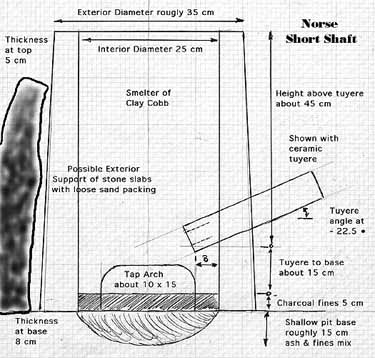
Figure 1 - Norse Short Shaft Smelter
'Econo Norse'
The Econo Norse was invented quite literally on the spur of the moment. It is intended as a demonstration or test furnace, constructed of easily available materials, that can be quickly assembled. All the components are quite modern. It does however share the same rough dimensions as the historic furnaces. This furnace was run for smelts 6 through 9, and has proved a good version for teaching purposes.
The core of the furnace is a circle of eight standard fire bricks (cm 11 wide x 5 tall x 22 long) set on end. This yields an internal diameter roughly 25 cm. Three rows of similarly arranged bricks make the required height of about 60 cm. The bottom ring has one full brick placed over two half bricks to form a tap arch. Either a gap in row two or a specially drilled brick serves to mount the tuyere. The individual courses of bricks are held in shape with a couple of loops of steel fencing wire during positioning. Once the cylindrical stack is in place, the whole is surrounded with a piece of thin sheet metal (also wired closed). The gap between the metal and the bricks is filled with insulating material. Several different mixtures have been tested, with the most effective being found to be a blend of 50/50 wood ash and course sand.
One of the other great advantages of the Econo Norse is that it is quite easy to disassemble in a controlled manner - even at smelting temperatures. This allows for easy extraction of the completed bloom. It also makes it relatively simple to convert the hot smelter into a large forge for the compacting of the bloom into a finished bar.
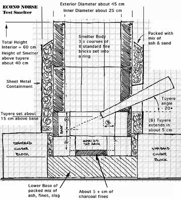
Figure 2 - Econo Norse Smelter
Air Systems:
The earliest smelts in the series under consideration here were guided by more theoretical considerations, plus being based on the ongoing work of other experimenters (most notably P. Crew (7). Smelts 1 through 5, in retrospect, clearly show the effects of an under blown bloomery. A smelt with low air volumes can produce workable metal, but at the trade off of greatly extending the overall duration of the process. The iron produced is also most likely to consist of smaller fragments distributed through the slag mass, rather than as a single solid bloom. The effect of low air volumes over long duration is seen in traditional African iron smelting methods . (8)
It has been demonstrated by Sauder and Williams (2) that a successful smelt is most likely when high volumes of air are supplied . They have suggested that an ideal rate of 1.2 to 1.5 litres per minute for each cubic centimetre of smelter base cross section. For the smelter size that has come to be standard for this experiment series (average between 25 to 30 cm diameter) this translates to effective air rates of between 560 to 1060 litres per minute.
Norse Double Bag
The shape of the very earliest experiments was guided by a desire to emulate historic Norse forms. One of the primary features was thus the use of a reconstruction Norse Double Bag bellows system. Unfortunately for experimenters, the artifact evidence for these bellows is almost nonexistent. There are no surviving physical remains, and only two known period illustrations. The most useful is the wood carving of a blacksmith and assistant at work on the Urnes Stave Church at Hyllestad Norway, dated to the late 1100's. This is a side view, shown in relation to a human figure that is operating it. From this illustration, which contains many other details recognizable to a working smith, it is possible to derive estimates for length, bag opening and even suggestions of the body position of the operator. The outlet air can clearly been seen as employing a pair of tubes running to the bellows stone. The second illustration is from a rune stone carving at Ramsund, Sweden. This is more cartoon like, and the image of the bellows, seen as a top view, is not directly tied to a human figure. It does however, give some indication of both the proportion of length to width and the size and position of the air intake in the top plate.
From 1998 to 2001, a number of trial version bellows were constructed based on these historic measurements. Experience gained from the use of each at a Norse type charcoal forge lead to variations that provided marked improvements in durability and effectiveness. The fourth version has proved to be the best all round design, and several of this pattern have been produced. The rough size is 70 cm long by 50 cm wide (including handles). Each of the main chambers is about 50 cm long by 25 cm wide. In use, a comfortable lift of the top plate is about 30 cm (at the handle end). The air inlet is 10 cm in diameter, using a simple one piece leather valve that is attached across the hole at top and bottom across the hole. There is no valve on the outlet end, which is composed of a pair of 2.5 cm inner diameter steel tubes. These are linked to the tuyere via a leather Y coupling constructed with flat sides.
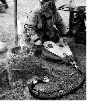
Figure 3 - The Norse Double Bag Bellows in action.
At Early Iron 1, note smelter set into shallow pit.
In use, the operator is raising (filling) one side chamber while he depresses to exhaust the other. A distinctive snap of the wrist at the top of each stroke is required to maintain a constant flow of air down the outlet tube. This, plus the resistance through Y tube, keeps exhaust air from draining back into the chamber being filled. It has also been found that a ratio between inlet and outlet diameters of 4 : 1 is important to the correct functioning of the system.
Several different handle shapes have been tested. Individual users will often ignore the handles and grasp the end of the top plate - the same hand position seen in the Urnes church carving.
Average air delivery is about 2.2 litres per stroke, calculated by counting number of stokes required to fill a large plastic garbage bag of known volume. In use it has been found that the average operator can maintain an effective pump rate of roughly one stroke per second. This means a air volume to the smelter of approximately 130 litres per minute. In practice it has proven best to have three operators available, rotating each through a fifteen minute shift.
Electric Blower
A number of mechanical air delivery systems have been utilized for portions of individual smelts. (Often for the simple reason of equipment failure while a smelt was underway!). Starting with experiment number 6, a dedicated electric blower (from old vacuum cleaner) was used. This blower was matched to an electric supply that could be modified via a light dimmer switch, thus creating a simple speed / volume control. This system was latter calibrated for delivery volume by use of a vane type anemometer.
This blower system dependably produces air volumes ranging from about 170 litres per minute at its lowest setting up to 850 litres per minute at full speed. This brackets the volumes available through use of either the Norse Double Bag or the Norse Über Bellows.
'Norse Über Bellows'
Smelts number 11 and 12 were designed as public demonstrations of a possible Viking Age smelt, with an attempt made to limit equipment as much as possible to those which might have been available circa 1000 AD. With the technical requirements of higher air volumes than can be produced from the smaller Norse Double Bag bellows in mind, it was decided to design a more speculative piece of equipment. The Norse Über Bellows was the result. It keeps the form of the smaller bellows, but doubles the linear dimensions, thus potentially increasing the air volume produced by a factor of eight.
The individual bags have a length of 100 cm, and a width of 20 cm. Air intake was achieved through a set of three holes in the upper plate, each 10 cm in diameter. These were fitted with simple leather flap valves, stiffened by gluing two half circles of thin metal on their inside surfaces. Rather than leather, the bags themselves are constructed of heavy canvas, covered with roofing tar to make them air tight. This was done primarily for economic reasons.
A typical operator will raise the bag to a height of about 50 cm for each stroke. Due to the size and weight of of the individual plates, it was found that a constant pumping rate of roughly 8 to 10 strokes per minute could be maintained. Operator fatigue was such that it was found that individuals had to be switched every 6 minutes, with a team of at least three required in rotation. Delivery volume has been calculated mathematically only. The volumes are estimated at an effective maximum of 90 litres per stroke, thus roughly 900 litres per minute.
This bellows was constructed with each of the individual outlets from the bags leading into a square box mixing chamber. There are no valves on the downstream sides of these 2.5 cm holes. From here a single tube extends to the flexible coupling and tuyere. In practice, it was found that this system was less than ideal. For the early part of each smelt, this bellows clearly was producing the required air volumes (as judged by burn rate of charcoal). In both experiments, there was a dramatic drop off of performance, about three hours into the sequence. This point is normally when the initial slag bowl is forming just below tuyere level. Later analysis revealed that as resistance at the tuyere increases, air is flowing backwards from the mixing chamber. In effect the operator begins to merely shift air from one bag to the other.
In both experiments (10 & 11), the smelts were 'saved' by reverting to an electric blower for the balance of the smelt.
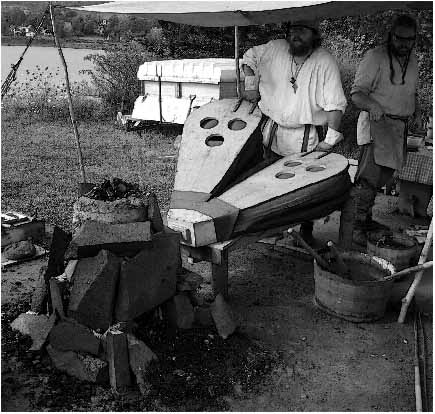
Figure 4 - The Norse Über Bellows at the Viking Age smelt for CANIRON 5.
Note the placement of its pole frame and the slack tub with tools close to hand.
Photograph by Ryan Scranton
A general survey of archaeological finds related to smelting and casting showed that the most common interior diameter for tuyere tubes of all types was 2.5 cm. For this reason, all the tuyeres used have been selected for this size, regardless of the material from which they are constructed.
The air supply in most cases has been fitted to the tuyere via a length of flexible hose, attached to a T shaped fitting ( Figure 5 ) . The assembly is constructed from standard 1 1/4 inch OD galvanized pipe fittings, allowing for ease of modification. A T connector is set so the inlet air is supplied at 90 degrees to the tuyere. An end cap with a clear viewing plate is fitted opposite the tuyere. This arrangement allows for direct viewing of the smelter interior down the tuyere. The viewing port can be unscrewed, allowing for any blockages to the tuyere to be cleared with a long steel rod. ( A process that has come to be known as 'rodgering'.) This system was adapted from that used by Sauder and Williams (9) .
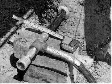
Figure 5 - Standard air connection method, showing view port.
At smelt #3, using steel pipe tuyere.
The two earliest smelts, and the two Viking Age presentation smelts (numbers 10 and 11), did not use this system. In these cases, the outlet of the bellows used was attached directly to the tuyere via a cylinder of leather. It has been discovered through experimentation that some form of leather coupling should be included along the outlet tube to tuyere chain when any human powered bellows is used. This flexible joint reduces any jerking from the action of the bellow exerting force on the tuyere.
Steel Pipe
In an attempt to standardize (and reduce cost), the bulk of the smelts have used industrial steel pipe for tuyeres. 'Schedule 40' mild steel pipe with an outer diameter of 1 1/4 inches has been used. This material has an interior diameter of the desired 2.5 cm. Typically this has been cut to roughly 30 cm lengths, with a number of replacements on hand for each smelt.
In the high operating temperatures of the smelter, the steel pipe burns away relatively quickly, often resulting in several replacements being required over the course of a smelt. Shrinking pipe tuyeres have also contributed to excessive erosion of specific smelter walls. These are both serious negative effects. (Smelt 3 failed when this burning back actually melted entirely through the smelter wall above the tuyere and stalled the reaction.) The drawbacks are balanced by the fact the standard pipe is cheap and easy to replace.
Forged Copper
A suggestion by Dr. K. Smith on the possible use of copper tuyeres historically (10) led to some experimentation with this material. Several tuyeres were forged from differing thickness of scrap copper plate and tested at a workshop in February 2005.
Two of these tuyeres were formed from 1/8" thick (about 3 mm) copper sheet. The interior diameter at the smelter end was roughly 2.5 cm. At this point, this style of tuyere has only been tested in conjunction with the Econo Norse (brick wall) smelter, in experiments 7 through 9. Although it preformed well for smelts 7 and 8, the copper melted away quickly in smelt 9.
During this workshop, Sauder, Williams and McCarthy worked with a tuyere forged from 1/4 inch thick (about 7 mm) plate. The forming process created a conical shape that varied in thickness from roughly 3 mm at the air supply end to about 7 mm thick at the smelter end. The interior diameter was approximately 20 cm in the smelter. This copper tuyere proved extremely durable - when used in conjunction with the thin walled 'Flue Tyle' test furnace they were developing. A similar heavy copper tuyere was used for smelt number 12. It has been found that the key to successful use of any copper tuyere is to ensure that as little as possible of the material is in contact with the furnace walls. Outside of the smelter, the high conductivity of the copper allows it to radiate away the heat its working tip is exposed to.
Ceramic Tube
When purchasing clay supplies in June 2005, an ideal ceramic tuyere was found to be commercially available. Designed to be supports for pottery kilns firing porcelain clays, each is a straight cylinder 30 cm long. The tube has an interior diameter of 2.5 cm with a wall thickness of roughly 1.2 cm (1/2 inch). Each is rated to withstand temperatures in excess of 1200 C - close to the operating temperatures inside an iron smelter. These tubes represent an inexpensive and standardized pre formed tuyere for continued experiments. Only one smelt in the series covered by this report used one of these tubes, but the performance was found to be excellent.
The physical process inside a smelter has been clearly described in some detail by A. Espelund. (11). Simply put, the air blast supports combustion of charcoal. This produces a column of extremely hot carbon monoxide gas that rises up through the charcoal contained in the body of the smelter. Individual ore particles, added to the top of the smelter, fall down through this column. The rate of fall is effected by their size relative to the size of the individual charcoal pieces. As the ore particles fall, they are heated, and the iron oxide of which they are composed reacts with the gas. Oxygen is exchanged, creating carbon dioxide gas and leaving metallic iron particles. These particles, while not molten, are close to the welding temperature and thus 'sticky'. At the bottom of the smelter, just below and in front of the tuyere, they will sinter together to produce the bloom. Iron rich slag will formed a bowl that surrounds and covers the developing bloom. It is through manipulation of the liquid slag pool that the amount of carbon incorporated with the iron can be controlled.
The first thing that these experiments have established is an effective design for the smelter itself.
One primary reason some of the earliest smelts did not succeed was that the smelters were simply too short. For smelts 1 & 2 this clearly did not allow enough time for the ore particles to come to an effective temperature to permit reaction at all. Once the distance from the tip of the tuyere to the top of the furnace was increased to at least 40 cm, there was enough 'stack time' for the heating and required reduction reaction to take place.
Starting with experiment 3, although a larger top reduction column was used, the correct layout of the base area of the smelter needed to be determined. Allowing for a large enough area below the tuyere was found to be important for two reasons. First, a suitable space needed to be provided to allow for the growth of the slag bowl and the developing bloom. It was also found that an insulation layer of lightly compressed charcoal fines would influence the position of the slag bowl. Too little space below the tuyere would cause the slag pool to form too high, quickly drowning the air flow. Even a short loss of the air flow would stall the production of heat, effectively freezing the entire reaction in mere minutes. The most dramatic failure to maintain a correct relationship with the position of the tuyere and the level of the base occurred in smelt 4, when slumping clay moved the tuyere to within a mere 3 cm from the lowest point of the earthen base.
Starting with experiment 5, an effective overall layout for the smelter had been established ( figure 1). The tuyere is mounted about 20 cm from the wall base. Inside the smelter, a layer of compressed charcoal fines determines the starting hearth bottom.
A theoretical means for determining the relationship between tuyere position and location of the starting bottom of a small smelter was determined by Sauder, Williams and McCarthy during the February 2005 workshop session.
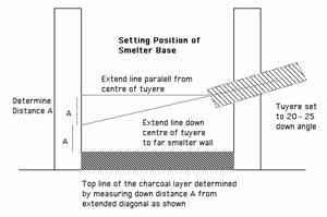
Figure 6 - Determining Smelter Base
This method has been employed to set the rough depth of the smelter bottom starting with experiment 7.
For smelts 3 & 4, the clay structure was prepared several weeks in advance and allowed to slowly air dry. Due primarily to the guidance of M. McCarthy during smelt 4, it has since been established that it is not necessary to allow for extensive drying times for the clay smelter walls before a smelt. Although some cracking of the walls will result, the structural aspect of the straw cobb makes this only a superficial effect.
It has been common practice to pre heat any structure with split wood as the first step in a firing. With those structures of raw clay, this step lasts until the outer surface stops 'steaming off'. Typically this phase lasts 30 - 45 minutes, with no air blast used. At this point the tap arch is sealed off, then burning of wood continues using a gentle air blast, normally for a further 15 minutes. For the last 15 minutes of the preheat, rough ungraded charcoal is used to fill the smelter and the air blast increased. At this point a switch to the graded charcoal is made, and the main progress of the smelt begins.
After preheating, the next stage of the smelt is waiting for the entire stack height of the smelter to ignite , which typically takes another hour. The total height of this column of hot gas and burning fuel is somewhat dependent on the total volume of air available through the tuyere. As the available height of the high temperature carbon monoxide represents the working reduction area of the furnace, ideally this column should be a tall as possible. It has been determined with an air volume of roughly 600 - 800 litres per minute, applied inside the standard smelter diameter of 25 - 30 cm, this ignited column will be roughly 40 cm tall. This places the top of the ignited charcoal only a few centimetres bellow the lip of the furnace. As maintaining the reaction area is critical, fresh fuel must be added constantly. It should be mounded up above the level of the top of the furnace.
As well as watching for the top of the ignition area to reach just below the top of the furnace, the consumption rate of charcoal is carefully monitored. It has been found through experience that an ideal burning rate is the consumption of roughly 2.2 kg (a standard 5 lb pail) of charcoal every 8 to 10 minutes. It has been found that maintaining this consumption rate constant is also critical to the success of any smelt.
Once the entire smelter volume is up to working temperature, addition of individual ore charges begins. This is done via a standard long handled scoop, ideally one that holds between 1/2 to 1 lb (250 - 500 gm) of prepared ore. For the balance of the smelt, ore is added by 'scoops', rather than specifically by considering total weights. Ideally the ore charge is distributed evenly through each charcoal bucket, and sprinkled over the smelter mouth (rather than being applied as a single slug of material)
Typically a number of single scoop / charcoal charges are added at this initial phase. A rough idea of the position of any given ore charge can be estimated by observing the drop of the charcoal. In the sizes used here, a standard bucket fills about 10 cm of the smelter cylinder. This means that any specific addition of ore will take roughly four charcoal charges worth of consumption to hit the important tuyere level. With the time interval per addition maintained, this translates to any given particle of ore being inside the reactive gas column for about 30 - 40 minutes ( A ).
Typically at about the time the first ore charge reaches tuyere level, the furnace will suddenly 'take off' with consumption rates rapidly climbing. (This expected at roughly at hour two of the main smelt sequence). The heat in the smelter, as measured by consumption rate with a fixed air volume, is controlled by damping the reaction by adding increasing amounts of ore within each charcoal charge. This is done in incremental steps as charcoal addition continues. Peak additions vary between individual smelts, but commonly reach as high as 2 kg ore added every 8 minutes.
As the slag bowl containing the growing bloom enlarges, it begins to fill the bottom of the smelter. The level of the liquid slag thus rises, eventually coming up to the position of the tuyere. The air flow will literally 'blow bubbles' into the liquid slag. This produces an extremely distinctive fluttering sound at the tuyere. If the level of the slag is not adjusted, it will eventually drown the tuyere. The interrupted air flow stalls ignition, and within mere minutes the entire thermal reaction stops and the smelter freezes.
The quickest way to adjust for this problem is to tap off some of the liquid slag volume. In some cases this process may take place on its own, producing what A. Esplund calls an 'incontinent furnace'. The liquid slag is hotter than the solidified bowl beneath it, so it may melt through the bowl and run through cracks in the lower structure of the smelter. In a smelter constructed with a tap arch, it is possible to expose the solid base of the slag bowl and using an iron probe, poke a hole up into the slag pool. Care must be taken here however. If the top surface of the bloom is exposed, the air blast may wash over the bloom itself. At the temperatures present inside the smelter, the blast from the tuyere may act in the same fashion as a cutting torch, literally burning away a grove into the metal.
If time permits, it is more useful to attempt to lower the entire slag bowl. As the bloom tends to form just below the tuyere, dropping the slag mass allows more space for a larger bloom to accumulate. By raking out the charcoal fines that were packed at the smelter base, it is usually possible to leave a gap below the slag bowl. Sometimes this mass is hot enough to sag under its own weight once this support is removed. By poking a hole into the liquid above, then allowing it to run into the space created, the greater heat of the liquid will radiate up into the slag bowl to accelerate this sagging process. These techniques can be done through a relatively small tap arch space.
Careful assessment of the quality of the liquid slag is also important over the operation of the smelter. Initially, slag which is frothy and bubbles as it runs, is somewhat viscous, and has a greenish cast when cool is created, This is a material composed primarily of silica / alumina. Its source is from impurities bound up with the ore and primarily melting of the clay smelter walls, chiefly from around the tuyere. Other than helping to maintain the heat inside the smelter, this material is basically waste and can be discarded if too large a volume is present.
In the latter part of the smelt, a slag of quite different appearance will be generated. This material is dark black when cooled, heavy, and runs almost like water. This is iron rich fayolite ( B ), and has been found by Sauder and Williams ( 2 ) that recycling of this material is an important factor in creating a solid workable bloom. By creating an apron of charcoal fines in front of the tap arch, it is possible to collect this material without incorporating additional impurities (sand or earth). Ideally the flow is allowed to cool only to the point it can be picked up with tongs and then added to the top of the smelter. Recycling of this slag serves to fill in any gaps that exist in the spongy surface of the bloom, effectively recouping any iron from the slag back into the bloom.
As the size of ore additions per charcoal charge increases, some decision must be made about just how large a bloom is desired. This choice will be primarily determined by how well the smelter is operating, and also dependent on which extraction method for removing the bloom is to be employed.
Once it has been decided that the bloom has grown to a desired size, the burn down phase begins. Raw ore is no longer added, but addition of charcoal continues. The rate of drop is used to roughly determine the relative position of the last ore charge, as described above. This process continues until it is estimated that this last ore has hit tuyere level.
At this point no further charcoal is added and the furnace is allowed to burn down. Normal practice has been to let the charcoal surface drop down to just above the level of the tuyere, perhaps 2/3 of the upper volume now empty of fuel. This marks the point were the extraction of the bloom is undertaken. Details of the two likely extraction methods are described under 'Working Patterns' below.
Air Supplies:
The discussion of the various air supply systems used, and how their available air volumes have affected the course of individual smelts has already been discussed. This suggests three main possibilities for the Viking Age.
First, it may prove possible to create a small bloom inside the standard sized smelter by working with a low air volume over an extended period of time. The failure of a large number of other experimenters employing low air volumes, as well as the conduct of the earlier smelts in this series, suggests that this may not prove possible. Low air volume smelts appear to at best create small sized and lacy or bubbly blooms, which in turn are extremely difficult to consolidate into working iron bars. This also contrasts quite sharply with the quality of known artifact blooms, which are generally quite dense and well consolidated. This suggests that the single Norse Double Bag bellows is a tool primarily intended for the blacksmiths forge. Assuming the measurements drawn from the extremely limited historic sources have permitted an accurate reconstruction, it is clear that this unit can not possibly produce the high volumes of air which have proved are required for truly successful smelts.
Second, although a single Norse Double Bag Bellows has limited air delivery, a number of these smaller units in combination could certainly provide the air volumes required. At a delivery of 130 litres per minute each, linking four or five would deliver a total in the lower range suggested as effective. This number is interesting - as a single whole goat or sheep skin would naturally provide a total of six attachment points (four feet, tail and head) that would allow to link the required number of bellows and attach the outlet for the tuyere. With the addition of an inlet only valve at each attachment point, plus the use of a plank with a stone weight, a constant air flow to the tuyere would be created. This is a more ideal flow than that produced by a direct hook up of a single bellows, which tends to pulse its air delivery because its action. It may also prove possible to vary the air delivery pressure by modifying the stone weight used in such a system. (Modifying delivery pressure will shift the location of the 'hot spot' inside the smelter. This in turn can positively affect the size and shape of the developing bloom.)
This suggests a possible effect on the social organization surrounding certain types of smelting operations. With small forge buildings often found on Viking Age farmsteads, individual family groups are likely to also have owned the Norse double bag bellows needed to heat them. If multiple bellows are required for smelting however, this suggests smelts undertaken on a seasonal basis may in fact be a community based activity. Like house raising, ship building and other high labour projects, these smelts might have gathered together a number of local households, perhaps then moving in rotation among them. Those researchers knowledgeable in social structure or rural lifestyles are certainly encouraged to examine this possibility.
Third, the ramifications suggested by the Norse Über Bellows solution to air volumes could be examined. This is a large and specially built piece of 'industrial' equipment using significant raw materials. It is unlikely to have been within the scope of the seasonal iron smelt, but certainly worth the effort to a full time smelting operation.
Because of its size, it may be possible to establish the marks of its footprint on the ground, most especially when examining those smelters which have been reused multiple times (as evidenced by repairs to the internal lining at the tuyere). At the very least, its position my be indicated by a void clear from ash, charcoal and slag fragments.
For the first prototype used in these experiments, the bellows was attached to a simple frame on four post legs. This allowed the whole unit to be mounted so it was canted at around 20 degrees down from horizontal - about the same angle as desired for the tuyere. This served two functions. First, it made for easy attachment and straight line flow into the the tuyere. It would have been even more effective to have set these posts into the ground a short distance to stabilize the entire unit. Because of the overall triangular shape of the bellows, such post holes would be distinctive if discovered.
Second, the angle elevated the working end so to position the handles at an ideal working height for the operator. This turned out to be more theoretical than actual. Although the three workers were of similar height, their combination of arm and leg lengths proved quite different. In practice what was comfortable for one turned out to be awkward for another. It also happened that as individual fatigue over the hours of labour effect each, widely different plumping techniques developed. The solution to these differing requirements was to dig a shallow rectangular trench at the operator end of the bellows. Individuals could quickly adjust for what they found personally most effective by standing in the trench to stand upright, or placing a couple of planks over the hole if wanting to work more bent over. This is the kind of feature that would prove puzzling if came to light in an excavation. Perhaps some of what are described as 'slag pits' may be nothing more than an attempt to backfill such a trench with waste.
Working Patterns:
There are two ways that a final bloom can be extracted from the smelter. Each presents different problems, and has in turn different advantages for the iron master. The two methods will also present different physical remains which may prove suggestive to archaeologists.
Sauder & Williams favour pulling the bloom, along with much of the clinging slag mass, out of the bottom of the smelter. This is a method better suited to large sized blooms, and requires smelters set totally above ground or having quite large pits in front of the structures. It should be noted that the smelters used by these two experimenters have been constructed with elevated bases to ease this process. Typical blooms they create are also large, with as much as 20 kg being common. One other advantage to this method is that the workers are able to shield themselves from much of the intense heat of the smelter interior by keeping their bodies to either side of the smelter as its base is opened, and by working with long handled tools at full arms reach as much as possible.
This method does require either greatly enlarging the size of the tap arch, or digging away underneath the base of the smelter - often both. As the slag mass will grow to fill most of the available space, this normally means creating a gap at about as wide as the width of the smelter interior as measured at tuyere level. There typically is considerable damage to the lower front of the smelter, especially when removing a large bloom. This opening should be seen in any smelter remains when this method was used. If the furnace was later reused, any repairs made should be clearly visible as well.
When the furnace is opened at the bottom front, any burning charcoal and loose slag fragments are raked away from the inside of the smelter below the slag mass. When the smelter is set above ground, this hot debris is raked forward of the smelter, and then shoved off to either side out of way of the workers. Next the the slag bowl itself is chiselled off the sides of the bloom, a long iron bar with a sharpened flat tip ideal for this task. This tends to break much of the slag bowl, still yellow hot, into large lumps. These are in turn pulled out and tossed to the sides, and should be found laying on top of the initial ash and charcoal deposited.
Next the hot bloom itself is pulled out of the smelter, using a hooked iron bar or special large bloom tongs. As this is done, the burning charcoal remaining above the bloom is pulled free, and tends to fall down to the bottom of the smelter and spray outward from the opening.
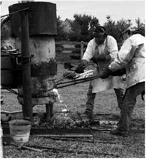
Figure 7 - Lee Sauder (R) and Skip Williams starting to pull out a completed bloom.
The furnace is their original test bed, the 'African Queen'. Staunton VA, 2002
Normal practice at this point has been to drag the mass, still with considerable lacy iron material and slag attached, over to a striking surface set on the ground. The surface is worked over with sledge hammers, first to remove any slag still clinging to the surface, which can be easily distinguished from the solid bloom underneath by both a different texture and the faster rate at which it cools. At the same time, an attempt is made to compress any of the lacy textured iron 'mother' - sintered and reduced iron which has not securely attached into the main bloom mass. This process tends to result in a spray of pieces (slag and loose metallic fragments) ranging up to fist sized around the striking surface. A flat stone would prove the ideal anvil surface for this process, needing to be large enough to be several times the weight of any bloom if it was to remain stable under the hammering. Work at this stage is undertaken at a furious pace, as the bloom is white hot when pulled from the furnace, and as discussed, reheating is extremely difficult.
It has been found (suggested by M. McCarthy) that further working after this initial consolidation is much easier if the bloom is moved and hammered on the top of a green hardwood stub set at classic blacksmithing height (roughly 60 - 70 cm). Such a stub should be at least double the diameter of the blooms being worked, perhaps 40 to 60 cm in diameter. Ideally it would also be dug into the ground to some distance to keep it stable. Depending on the consistency of the bloom, considerable liquid slag can often be seen being driven off the surface under the hammer blows. As the metallic bloom is often still at a welding heat, these remains should consist of a distinctive pattern of smelting slag mixed with large hammer scale. Hammer strikes typically spray materials more to either side than front and rear. Any particles are further prevented from flying backward as they intersect with the hammer operator! If the fragments are heavy enough and occur in enough number, it may be possible to estimate the number and position of the work team by looking for the pattern of voids caused by the bodies at work.
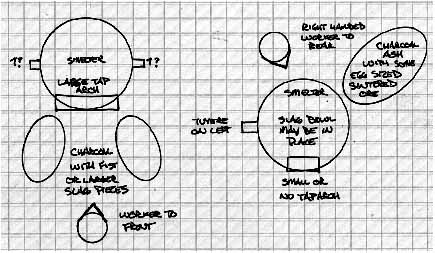
Bottom Extraction / Top Extraction
Figure 8 - Likely debris fields around a smelter.
The other method of extracting the bloom is withdrawing the mass out of the top of the smelter. This is the main method which has been used throughout the experiments described here. This method is ideal for smaller sized blooms, more typical of those found from the Viking Age. Its main disadvantage is in the extreme heat faced by the individual who physically uncovers and pulls out the bloom from the incandescent interior of the smelter. The entire process needs to be undertaken with a reduced, but still present, air blast through the tuyere. This keeps the slag bowl soft and keeps the liquid slag pool from freezing and locking the bloom within it. There are a number of advantages, however, that have lead this to becoming the method of choice over this series.
A smelter intended for the top extraction method needs only a small tap arch, suitable only for decanting liquid slag as required during the firing. Again this structure should be evident even on fragmentary remains.
In this method, a long handled metal scoop is required for the first step. This is used to scoop out all the remaining burning charcoal from inside the smelter, until the top of the molten slag pool covering the bloom is exposed. Assuming a right hand operator, this charcoal is typically dumped in a distinctive pattern to the rear and slightly across from the position of the tuyere and the bellows operator. This material may also contain lumps of partially reduced and loosely sintered ore which had not incorporated into the bloom (from the last ore charge added). In many of the experiments, some liquid slag itself was scooped out at the end of this sequence, resulting in a spray of molten iron rich slag droplets deposited on top of the charcoal.
The next part of the process is to use a log 'thumper' to strike the top of the bloom in place. As the bloom forms just below the tuyere, special care must be taken not to strike the tuyere itself. This process has several effects on the bloom. First, as the bloom is just at welding heat, striking it serves to compress much of the lacy 'mother' material into the mass - with less loss than the process used when the bloom is extracted before any hammering. The hammering in place also serves to loosen the metallic bloom from the congealed slag bowl underneath it. Next a bloom hook is forced down and underneath the edges of the bloom to pry the mass up and free from the slag bowl. Once loose, the large bloom tongs can be used to grab the metal mass and pull it up out of its position in the slag bowl and free of the smelter.
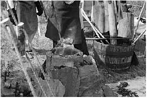
Figure 9 - Scooping burning charcoal before extracting the bloom from the top.
Note burning charcoal deposited to the right. Tap arch towards camera.
Photograph by Neil Peterson
If the air flow was cut at this point, the slag bowl, virtually intact, would freeze in place inside the smelter in one piece. It would display the well known concave / convex shape often found. The top surface would have some charcoal deeply embedded into the slag as a result of the pounding from above. The lower surface would have more the appearance of tendrils running down and around charcoal lumps.
Typically, much of the loose fragmentary material has already either been compressed or knocked loose from the bloom before it has been extracted. This allows movement directly to the raised stump for the consolidation step. One other huge advantage of extraction from the top is that there is very little damage (if any) to the structure of the smelter. If the process of extraction is preformed quickly enough, it is quite possible to fill the smelter with fresh charcoal, and with increased air blast quickly restart the fire. This allows for use of the smelter as a giant forge for further work on the bloom.
More importantly, as the smelter is not significantly damaged by this method, and retains the bulk of its internal temperature, it should be possible to immediately restart a second smelt. The main limitation would be the volume of slag already in position just below the tuyere.
Bloom Size and Quality:
Artifact iron blooms from the period of interest are often found as compressed 'pucks', in the range of 2 to 12 kg in weight. An 'average' bloom is about 4 to 8 kg in weight, and often shows a distinctive slice from one edge. ( 12 )
The shape of these blooms has certainly derived from an initial consolidation - immediately as they have been removed from the smelter. A typical, dense bloom will range from a rough foot ball to lens shape as it is removed from the smelter. The simplest way to handle the hot metal at this point is to compact it along the long axis, then set it on its edge and rotate it while compacting all those surfaces. The characteristic cutting of many artifact blooms from one edge would then follow. Experience from cutting several blooms (and through years at the forge) suggests that the iron master can judge both the density and rough carbon content of the metallic iron through the amount of effort required for these processes.
There appears to be some 'lower limit' to the quantity of ore that is required to provide for the creation of a dynamic slag bowl containing a workable iron bloom. Experiment 5, which was the last to use the Norse Double Bag bellows, used only 8 kg of ore. The result was a solid slag mass topped with more of a 'froth' of iron. When the mass was sliced and polished, ( figure 10 ) it was found that a thin film of soft iron was developing around individual pieces of charcoal - like a web of soap bubbles. ( 13 ) .
Figure 10 - The 'Pre Bloom Mass' from Early Iron 1, sliced roughly in half.
Note lacy metal 'bubbles' in the upper right corner. This area just below the tuyere.
Preparation and Photograph by Elizabeth Hendrix
Increasing the overall duration of this smelt would likely have resulted in this structure collapsing as the charcoal was consumed. It is suggested however that most of the ore that was added in this smelt had gone to the production of the slag bowl, and that the actual amount of workable metal produced would only have been a small fraction of the total ore weight.
Experiment 10, although experiencing some problems with air systems, may indicate something about this threshold. In this smelt, about 11 kg of a high iron content ( 65% Fe) taconite ore was added. The final product of the smelt was a highly condensed bloom estimated at about 3 kg. ( C )
The method as currently developed is more notable for how large a useful bloom is regularly produced. Extracted bloom weights (before serious consolidation) are typically in the range of 10 to 15 kg. Similar sized and sequenced furnaces have produced blooms into the 20 kg range. As a rough rule of thumb, the first three hours (including preheat) and approximately 1/3 plus of the total charcoal expenditure are used to reach the point in the smelter sequence where any bloom at all is starting to form. Obviously making a single large bloom is a far more efficient use of all resources than running two separate smelts to produce two separate 'half sized' blooms. When this ability to produce large blooms utilizing smelters of similar size to artifact samples is demonstrated, it raises the question - why are so many of the artifact blooms typically so much smaller?
The answer may lie not in the iron smelter itself, but with the Norse blacksmith. Examination of the existing artifact tool sets, although admittedly removed from the smelting operation, suggests that large sledge hammers were not part of the Viking Age tool set. The largest hammer in the Mastermyr find is 3.4 kg (7 1/2 lbs), with the next pair (most certainly single hand hammers) at 1.8 and 1.6 kg. The largest, fitted with a 85 cm handle (the longest that would fit in the chest) only compares with the smallest hammer used during these experiments for consolidation (at 8 lbs / 3.6 kg). ( 14 ) Most of the hammers used for experimental consolidation were in the 10 - 15 lb (4.5 - 6.8 kg) range. Particularly when attempting to work a large, dense bloom, a lighter hammer simply cannot strike with enough force to affect the mass significantly.
The second factor is related to the problem of physically heating a large mass of metal. All the work being described here is undertaken as quickly as possible, utilizing the initial heat remaining from the smelting process itself. Once the bloom approaches a measurement close to that of the diameter of the smelter itself, even the still hot smelter cannot supply enough heat to raise that bloom back up to effective forging temperatures. There simply is not enough room to pack the required volume of burning fuel around the mass to heat it. In this experimental series, the largest blooms (in the range of 7 - 10 kg) have not been worked into bars, exactly because of this same problem of how to reheat them. Hot cutting is also the only available option to reduce a bloom to more manageable pieces, even in a modern shop.
One conclusion is that historic blooms have been created in smaller sizes that what could have been easily achieved quite deliberately - specifically for ease in handling, forging and reheating.
Useful Tools:

Figure 11 - Smelting Tools
A number of specific tools have been created to suit specific tasks required over the course of the smelt. Several must have much of their length composed of forged iron (modern steel substituted). These are described here in the chance some artifact samples might exist. This is not considered likely however. The simple contours and long straight lines would make individual pieces ideal for reforging into other objects once they were no longer required for their initial purposes. Some likely dimensions are suggested, bearing in mind the physical requirements of the tasks and the structural limitations of bloomery iron as the material. The metal working ends of these tools would have been fitted to wooden handle. The most likely method would be to use a right angled tab that fit into a slot cut into a square cut handle, the shaft held in place with a simple ring collar. Ideal completed lengths are in the range of 150 - 180 cm. (The versions created for the experiments used cylindrical sockets fitted to dowels or poles.)
Probe ('Radner') - Typically a straight length of 1/2 to 5/8 inch ( in period iron likely 1.5 cm) square stock, with a shaft length at least the distance from top of the smelter to the base (about 60 cm). The tip is forged to blunt straight chisel shape. This tool used for removing blockages to the tuyere (by inserting down the tube). Most importantly used for creating holes in the slag bowl during tapping, cutting the slag mass and freeing the bloom from the smelter walls during extraction. It has also proved valuable to have an all metal version, which allows for hammering on the base end when more force is required.
Bloom Hook - Similar in size to the probe, the end is flattened and forged over the edge of the anvil to create a short hook shape (see illustration). This hook should be roughly 1.5 to 2 cm, a measurement which is critical. Too large, and the hook end will not fit between the smelter wall and the bloom. Too little and it will not get enough purchase on the bloom to exert much upward force.
Rake - This tool can use slightly lighter bar, and the metal end needs only be as long as the diameter of the smelter (about 30 - 40 cm). The tip is flattened for about 6 - 8 cm and bent at a right angle to the shaft. It is used to rake out material at the base of the slag bowl during tapping and any attempt to lower this mass. Also very useful when controlling the physical flow of molten slag when tapping.
Bloom Tongs - These are a specially created set of tongs used for lifting and holding the bloom. The bloom may be as wide as 15 or 20 cm when first extracted, and the jaws of the bloom tongs must be designed to securely hold a wide range of material sizes. These need to have extra long handles to provide gripping strength (and to keep the user back from the intense heat!). (Note that the blacksmith's tongs from Norse finds are simply too small for this task.)
Slack Tub - although not a smelt specific tool, the presence of a water tub within arms distance of the working smelter is essential. All of the tools above will require cooling frequently. In contact with the extreme heat at the interior of the smelter, it takes as little as one minute to heat the working end of a tool to an orange heat requiring cooling. Multiple use smelters might show the circular impression of the coopered wooden tub.
'Thumper' - This is the only all wooden tool used, suggested by a tool illustrated by Boonstra, van de Manakker & van Dijk ( 15 ). It is a piece of green timber, ideally hard wood (for its weight). A good working length has proven to be about 1 metre, with a diameter of roughly 10 cm. The tool is easier to use if it is fitted with a pair of smaller wooden handles that run parallel to the long axis. This allows the operator to stand above the smelter and lift the tool up and drive it straight down, increasing both accuracy of aim and power of stroke. The working end is soaked in the slack tub before use. (As this tool is basically a length of fire wood, the chances of ever recovering one are extremely unlikely!)
Charcoal Scoop - This tool would have roughly the same shaft length as the probe, but would end in a small D shaped scoop of heavy sheet iron, set at roughly 90 degrees to the shaft. A scoop of roughly 10 cm wide by about 6 deep has been found most useful. Ideally the back curve should be dished up with the front straight edge flat. This tool is only likely to be present if the top extraction method is employed (as described below)
Protective Gear - Although the whole concept of specially designed equipment to ensure worker safety is clearly an entirely modern concept, the working conditions at the smelter are such that without some protective clothing, extraction of bloom would simply be impossible. Heavy leather gauntlets certainly must be worn to protect the hands from the extreme radiant heat. It has been found that by completely soaking Norse style wool clothing in water, plus the addition of a bib style leather apron, the body can endure the heat (at least if working quickly over the smelter) during top extraction! The last item suggested is more speculative in nature, that being a leather face mask. A simple sheet of leather tied in place with two narrow slits for the eyes would serve to protect the face, again particularly a problem during top extraction. (Several modern protective face shields have actually melted in place on the wearer's face during past extractions.)
Time:
In the Viking Age Re-Creation smelts (numbers 10 & 11) it was decided to utilize time and record keeping systems that might have been available circa 1000 AD. Time interval was determined by the use of a simple water timer. This consisted of a clay jar, roughly 20 cm deep by 15 cm diameter. In the bottom a roughly 1 cm hole in the clay had been plugged with a layer of wax. In the wax a small hole was made with a heated wire (allowing for some adjustment of the hole size). Interval was determined by placing the jar into the water filled slack tub. Water would fill the jar from the lower hole until the buoyancy of the jar was over balanced and it would suddenly sink to the bottom. This was found to provide a relatively consistent measure of time. By adjusting the size of the hole, it was possible to 'tune' the length of the event. For these demonstration smelts, the jar was set to measure a six minute interval. This proved to be an ideal session length for a single individual to work the Über Bellows. Two such measures provided a workable time to judge charcoal consumption rates.
Total amount of charcoal, and more importantly ore added (both per charcoal charge and in total), were measured by moving coloured beads from one wooden bowl to another. A handful of small red (ore) and black (charcoal) glass beads were used for this purpose.
It has certainly been the experience of these smelts that some kind of record keeping is extremely valuable. With fuel and ore charges being required to be added over short periods, but over many hours duration, it has proven easy to get distracted from simple counting. As detailed in the description of a successful smelt, being able to measure a standard time unit of roughly 8 - 10 minutes has proved critical. This certainly suggests that Viking Age iron smelters used some method of establishing a standard time interval.
Above all, it must be clearly stated that the progress of the experiments has started from a largely theoretical basis, moved over to concentrate on learning one possible effective system, and now is in the process of working back to a possible historical model. The continuing problems with air delivery, and the frankly speculative solutions explored, certainly reminds all involved that these experiments may present A way to effectively smelt using Viking Age prototypes - but may not represent THE way used historically.
Current plans are to construct a dedicated area at Wareham for continuing experiments. This will consist on a levelled and revetted area, backing into a natural shallow bank about 1 meter high. The working area is to be roofed with sheet steel on a pole frame. This will permit extension of the working year, with sides tarped off, perhaps even into the winter months.
A series of earth banked smelters are planned. These will most likely be constructed of the proven clay cobb mixture, using the commercial Hawthrone Fire Clay. This material has proven quite durable, and should stand up to multiple smelts in the same furnace with minimal repairs between each.
The first smelt planned for June is going to be an attempt to create two smaller blooms, one after the other, in the same firing event. The first bloom will be extracted through the top as in the past, then a second work team will immediately move in and recharge the furnace for the production of another bloom. This idea of running a single smelter back to back is an extension of the observed small artifact blooms placed against the greater efficiency of creating a single larger mass once the reaction is started.
A second reason for this method will be to expand the number of team members who have direct experience managing an ongoing smelt.
Into September, there are two full Viking Age presentation smelts in the planning stage. The first will be at a private event outside North Bay over Labour Day weekend. The site is primitive, with no electricity available and even water having to be hand packed in a considerable distance. The second is a possible smelting demonstration in conjunction with DARC's annual living history presentation at the Haffenreffer Museum of Anthropology at Brown University in Rhode Island. Because these are both presentations to a general public, stress will be placed on process and effective communications rather than concern about the quality of the bloom produced.
The ongoing related experiment of recording the weathering of abandoned smelters will continue. Measurements and photographs will be made on a seasonable basis, with data and samples being sent to Dr K. Smith at Brown University.
A number of other specific experiments suggest themselves from questions arising from the initial experimental series:
- development of a small scale test smelter based on the Flue Tyle model.
- test smelt using 'red ore' material gathered from outside Haliburton ON
- long duration smelt matching air volumes to the Norse Double Bag
- test of a clay tuyere plate style furnace
- test of a slag pit style furnace
- testing of commercially available hematite grit as ore
Lee Sauder & Skip Williams Rockbridge Bloomery, Lexington VA
Mike McCarthy Hammer in Hand Forge, Cooperstown NY
The resulting professional association and personal friendship extended by these three individuals has and greatly assisted the experimental series discussed here. More importantly, they constantly strive to de-mystify the smelting process, and their enthusiasm is absolutely infectious.
Many core ideas recorded here have sprung up at late night discussions after a long day of group smelting. Every attempt has been made to attribute their individual contributions if at all possible. It is safe to say that without their guidance these smelts would be still unsuccessful (under blown and making cast iron at best!)
the DARC Smelt Team:
Kevin Jarbeau Dave Cox Neil Peterson
Assisting:
Ken Cook Marcus Burnham Karen Peterson
Vandy Simpson Gus Gissing David Robertson
These and other members of the Dark Ages Re-creation Company have formed the core team for seven of the thirteen experiments described here. Each is an experienced historic interpreter, with a good working knowledge and craft skills related to the Viking Age. Most have worked on major museum exhibits and living history presentations. It would have been impossible to mount the individual smelts without their willing labour. Individuals have also provided their skills in documenting each experiment and all have suggested improvements as the work has progressed.
Other Smelt Participants:
Smelt 1 - Parks Canada / L'Anse aux Meadows NFLD
Dr. Birgitta Wallace / Arne Espelund
Smelt 2 - DARC / Wareham ON
Dr. Kevin Smith
Smelt 5 - Early Iron 1 / Cooperstown NY
Michael Mahoney / Millard Wyman / Paul Burdon Elizabeth Hendrix
Smelt 8 - Smeltfest 05 / Lexington VA
Vince Petty / Vandy Simpson
Smelt 9 - OABA / Wareham ON
Neil Peterson / John Burton / Lloyd Johnston
Smelt 13 - Early Iron 2 / Cooperstown NY
Elizabeth Hendrix / Toby Bashaw
Smelts 1 / 4 / 12
Mark Pilgrim
...To Royal Oak Charcoal. Royal Oak has generously donated all the charcoal used for the bulk of these experiments. This continuing series would not have been possible without their support.
(A) The actual decent of any specific particle of ore is actually more complex than suggested. First, the size of any particle against the size of the charcoal particles surrounding it will determine how it may 'fall through the holes'. Individual charcoal particles are being consumed as they fall, so will be smaller and permit smaller gaps as they approach tuyere level, slowing this specific effect. Although ideally charcoal is being consumed at an even rate across the entire smelter surface, in practice the fire develops 'hot spots', which may shift and shrink during the course of the smelt. Typically, fuel is consumed more quickly just in front and slightly above the tuyere nozzle. This tends to move the charcoal, and thus ore, on a diagonal line towards any hot spot.
These effects are attempted to be evened out by changing the placement of the ore charges. Early in the smelt it is normal to distribute the ore in a fairly even disk over the entire surface. Later on it is normal to distribute the ore in a C shape, bracketing the tuyere location. As uneven burning is indicated by slumping of the surface charcoal, the ore should be placed at the 'high spot' on the surface.
The individual charcoal pieces may temporarily lock together, especially closer to the top of the smelter where they are larger. This can allow for a temporary gap in the pile as smaller pieces lower in the pile burn away. This support never lasts for long, but as the top web collapses, a dramatic drop of the surface of 5 or even 10 cm may occur. Obviously this will effect the even progress of ore particles down the column.
When charcoal is shovelled out during the process of extracting the bloom from the top, it is common to find lumps of partially sintered ore particles well above tuyere level. Obviously these larger pieces will move in an entirely different fashion than smaller fragments.
(B) The chemistry of slag and its formation is quite complex. For the purposes of the description, what is in fact a progression of slag types has been greatly simplified. When actually operating the smelter, the two primary types described will be seen, and managing these effectively is critical to maintaining an effective smelt sequence. As slags are extremely durable, and often represent waste products of the smelting process, they have been described in considerable detail by other researchers.
(C) Unfortunately, this otherwise successful smelt suffered a blacksmithing disaster in its very final stages. The physical conditions were punishing, with daytime temperatures in excess of 30 C over the course of the smelt. This smelt also marked the first use of the Norse Über Bellows, and the raw labour required to operate these was greatly underestimated. As well the working team was limited to three individuals, all dressed in Viking Age costume and working as much as possible with replica tools. (This smelt was intended as the dress rehearsal for the planned public demonstration at CANIRON 5 in August.) The bloom, although small, was quite dense when it was extracted through the top of the smelter. Initial consolidation was carried out working on a stone anvil laid on the ground. At this point the initial 'foot ball' shape had been reduced to a disk, with the smelter being used as a giant forge for the process. Deciding to compact the edges, a missing pair of tongs had to be found in the remote workshop. In the time this took, the bloom had slid forward in the smelter to rest right against the tuyere. Unnoticed by those tending the fires, the high temperatures and air blast overheated and burned away roughly a full third of the precious metal before the error was discovered.
KristJan Eldjarn'
'The Discovery of a Norse Settlement in America'
Anne Stine Ingstad
Universitetsforlaget - Oslo.
(2) 'A Practical Treatise on the Smelting and Smithing of Bloomery Iron'
Lee Sauder & Skip Williams
Historical Metallurgy, vol. 36 (2), 2002
(3) As analyzed by R. Hansen at Eramet, Prosgrunn in July 2001.
Data received in a private e-mail from A. Esplund, 25 July 2001.
(4) As analyzed by M. Burham at Sudbury, Ontario in February 2002.
Data received in a private e-mail from M. Burnam, 10 February 2002.
(5) Copy of internal STELCO document, Spring 2005
(6) 'The Coated Tile Furnace'
Lee Sauder & Skip Williams
Technical Handout, 2005
(7) 'The Experimental Production of Prehistoric Bar Iron'
Peter Crew
Historical Metallurgy v. 25 no. 1, 1991
(8) 'INAGINA, the last house of Iron’ (video)
Bernard Agustoni & Eric Huysecom, Directors
Department of Anthropology & Ecology University of Geneva, 1995
‘Dokwaza: last of the African iron masters’ (video)
N. David & Y. Le Bléis, Directors
University of Calgary: Dept of Communications Media, 1988
(9) 'Iron from Scratch'
Lee Sauder & Skip Williams
Technical Handout, 2000
(10) From a private e-mail from Dr. K Smith.
(11) ‘The Four Phases: Carbon - Gas - Slag - Metal and their Interaction in Bloomery Iron making’
Are Espelund
in ‘Prehistoric and Medieval Direct Iron Smelting in Scandinavia and Europe’
Lars Chris. Norbach editor
Aarhus University Press, 2003
(12) 'Iron in Archaeology - the European Bloomery Smelters'
Radomir Pleiner
Archeologicuy Ustoav Av Cr, 2000
(13) 'Viking Age Cobb Furnace and Resulting Bloom'
Elizabeth Hendrix,
MIT Field Report, 2004
(14) 'The Mastermyr Find - A Viking Age Tool Chest from Gotland'
Greta Arwidsson & Gosta Berg
Almqvist & Wiksell, 1983
(15) 'Experiments with a Slag-Tapping and a Slag-Pit Furnace'
Anneke Boonstra, Thijs van de Manakker & Wim van Dijk
in 'Early Iron Production - Archaeology, Technology and Experiments'
Lars Chr. Norbach editor
Historical-Archaeological Experimental Centre, No. 3, 1997
'Iron Making in a Roman Furnace'
Henry Cleere
Britannia, v.2, 203-217, 1971
‘Iron Production in Norway During Two Millennia’
Arne Espelund
Arkentype, 1995
'Ore, fire, hammer, sickle : Iron production in Viking Age and Early Medieval Iceland'
Kevin Smith
De Re Metallica: AVISTA Studies, v 4,183-206, 2005