 |
 |
 |
 |
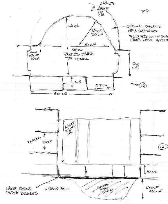
The theoretical layout for the test smelter |
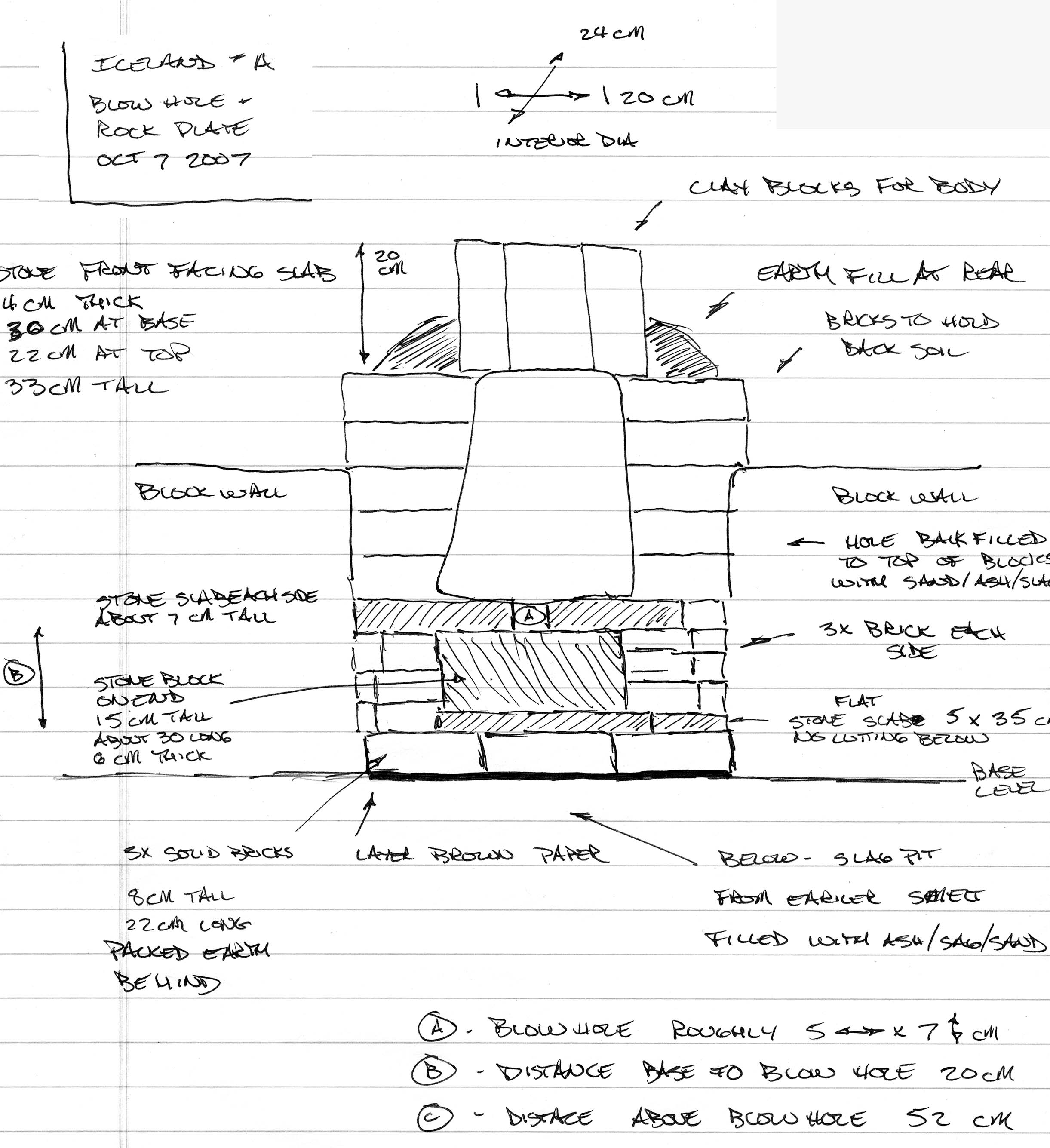
Details of the lower base level. | Smelter Construction details - front elevation |
Working set up - side elevation |
Initial Construction of Smelter
 |
 |
 |
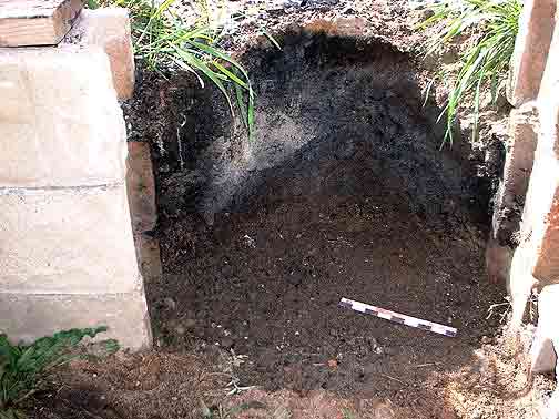
| The remains of the last smelt removed, new floor level filled with ash / sand / debris mix. | Layer of heavy brown paper laid to mark floor level | New base level established using packed soil, retained by line of bricks. |
 |
 |
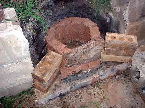 |
| Lower area of front smelter built up of stone slabs to a height of about 20 cm. Bricks to sides are not part of smelter, but used to retain earth fill to be added later. | Commercial potter's clay cut into roughly 6 cm thick slabs will make up the body of the smelter. | Showing the clay slabs laid in to the first (slag bowl) level. Soft waste clay was used as a mortar to seal the slabs together. |
 |
 |
 |
| Rectangular stones establish the blow hole space roughly 5 cm wide by 7 cm tall. Second row of clay slabs in place | Fitting the stone front plate in place. The stone slab was roughly 4 cm thick and extends about 20 cm across and about 30 cm above the blow hole. | A view from the top of the smelter, showing the fitting of the stone front plate. A mix of ash / sand / debris is used as back fill to stabilize the smelter. |
 |
 |
|
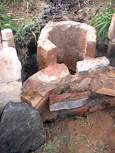
| A closer view of the inside of the smelter. The blow hole is just below the dark grey surface of the front stone plate. | The finished construction. |
Firing the Smelter
 |
 |
 |
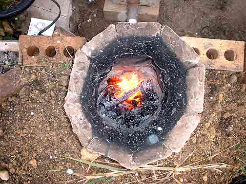
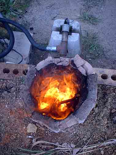
| Starting the pre-heat using split wood. Unlike earlier smelts, there was not a base set with charcoal fines. | The pre-heat continues with the bellows tube and air system in place. The tip of the steel pipe bellows tube is set just even with the interior wall surface of the smelter. | Short drying time for the solid clay left considerable moisture remaining. The result was serious spalling and cracking of the clay slabs, particularly at the top of the smelter. |
 |
 |
 |
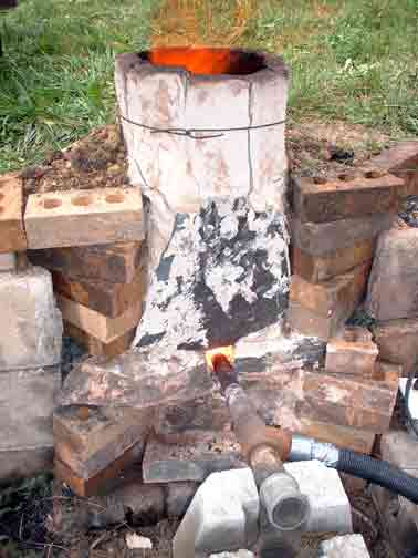
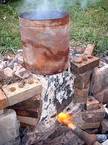
| As the pre-heat continues, the base area below the blow hole fills with ash and small charcoal. | Because of the excessive cracking of the top layer of clay slabs, this layer was removed and replaced with a metal cylinder. | With the open blow hole and high volume air, a significant amount of the blast merely blew back from the mount of the bellows tube. This image taken just after the first filling of the smelter with charcoal. |
 |
 |
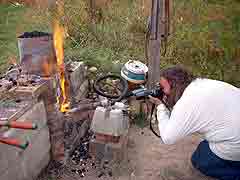 |
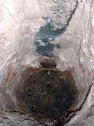
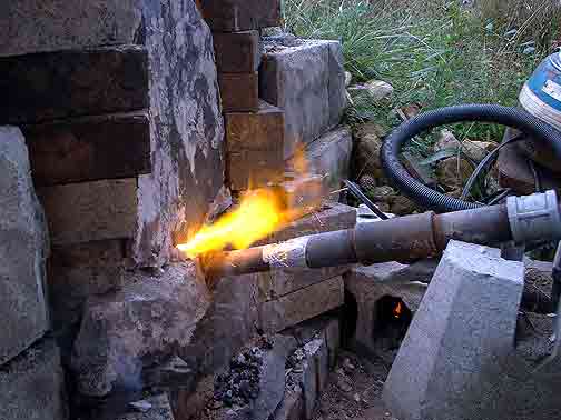
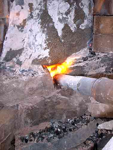
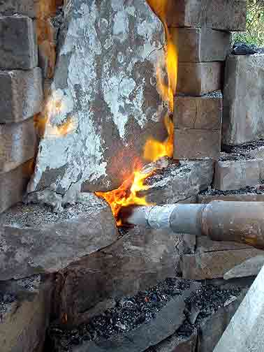
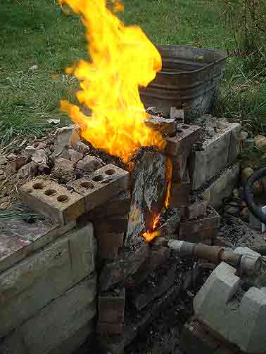
| About 35 minutes into the main smelt sequence, the first drip of slag is seen at the blow hole. | Fairly quickly, dripping slag solidifies across the blow hole, effectively sealing the bellows tube into a tuyere even with the inner surface of the smelter wall. | Neil attempts a 'down the kilt' shot of the inside of the smelter. Although the air blast is now sealed inside the smelter, the heat radiating off the stone slab was significant. |
 |
 |
|
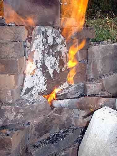
| Nearing the end of the smelt. Note the colour of the stone slab above the tuyere. | Into the burn down phase. The volume of charcoal in the upper metal cylinder has been consumed, so that had been removed. | The charcoal level is allowed to burn down to just about the tuyere level. This image just before the remainder of burning fuel is scooped out to expose the hot bloom in its bath of liquid slag. |
 |
 |
Continue for the EXPERIMENT
DATA |
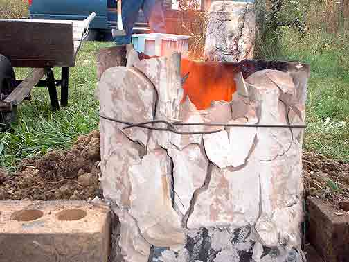
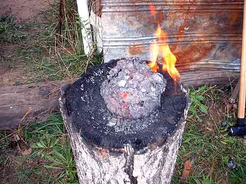
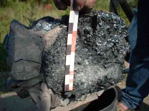
| The resulting 6 kg bloom just after some of the loose mother has been hammered off. Less compaction of the surface has been accomplished than normal - due to the exhaustion of the workers! | Just after the smelt. Some of the clay slab walls have fallen into the still hot interior. These were broken away during the extraction effort. The cooling bloom can be seen to the upper right. | Smelt in Progress Quicktime Movie (1.9 Mb) |
Excavating the Smelter Remains
 |
 |
 |
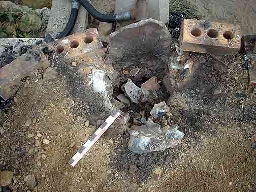
| Scaled image of the bloom as it would have laid in the smelter, along with two pieces of melted stone slag. | Remains of the smelter before starting excavation. The raw earth packing
shows discolouration from the heat. (note that scale here is not N/S) |
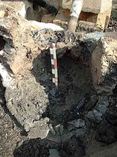
Upper area of the smelter directly opposite the tuyere. Note the cracking
of the clay slabs from the firing. (note that scale here is not N/S) |
 |
 |
 |
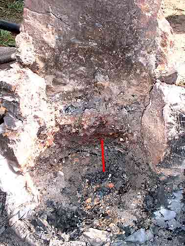
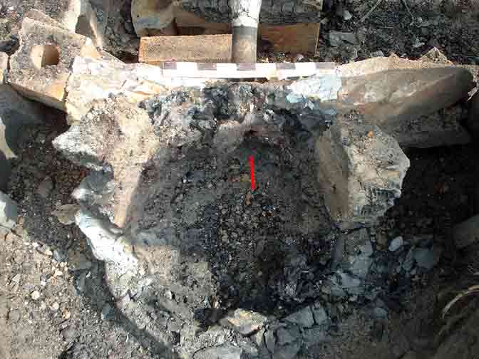
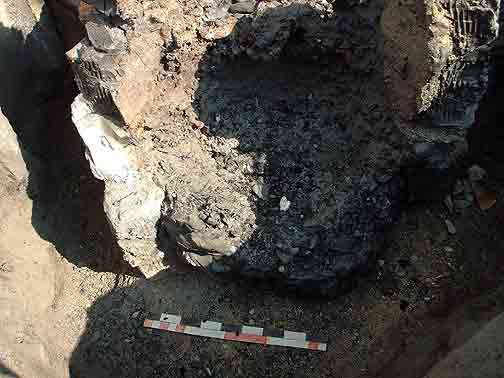
| As the smelter was de-constructed, the full extent of the cracking of the slay slabs was obvious. Individual pieces show the effects of heating. A range from slag covered surfaces through sintered ceramic to raw dried clay could be easily seen. | With those pieces of clay wall material that had fallen in removed, the top of the slag bowl was exposed. (A red line on the large image shows the direction of the air blast.) | With the top layer of earth packing removed, showing the top of the ash / sand / debris packing. |
 |
 |
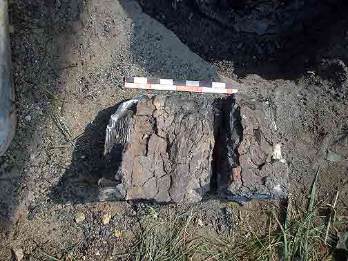 |
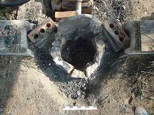
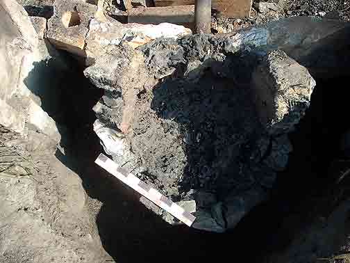
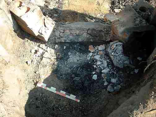
| Clay slab walls removed to just above the blow hole level (2 layers of 3) The stone slabs at the front of the furnace remain glued together by solidified slag. | Clay slab walls removed to about the top of the slag bowl level (1 layer of 3). The slag surface is exposed, but not cleaned of fine debris at this point. | A close up of the interior surface of one of the clay slabs. This piece from about tuyere level, taken from off to one side (about 3 o'clock from the tuyere.) |
 |
 |
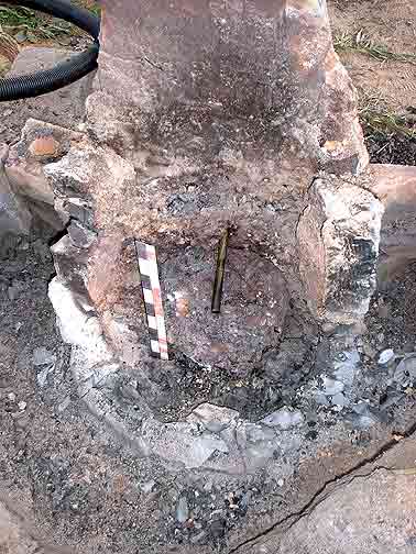 |
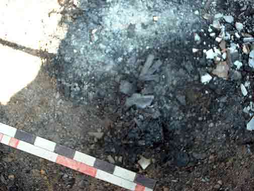
| A closer view of the top of the slag bowl with the direction of the tuyere blast indicated by a line. | Here most of the loose particles have been blown off the surface. A metal rod has been inserted down the tuyere to show its exact location and direction of air blast. | Scale in vertical measurement. The depression that contained the bloom is clear. |
 |
 |
 |
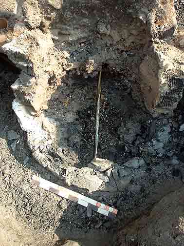
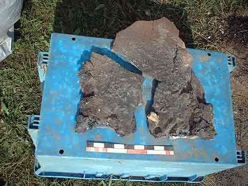
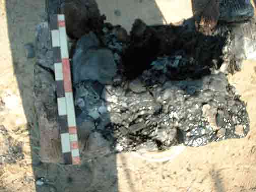
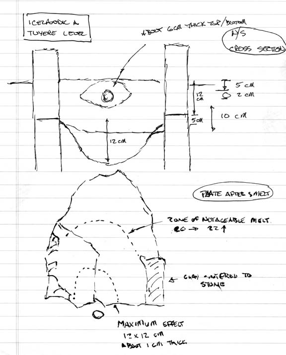
| With the front stone slab removed. The red line on the larger image again marks the air blast. | The stone front slab after it was removed. The heat effects above the tuyere area are clearly seen. The slabs original thickness of 4 cm has been melted back to closer to 1 cm just above tuyere level. | Lower interior with scale. |
 |
 |
 |
| Clearing away the packing material to the original base level | Removing the last of the clay slabs. The remaining pieces were firmly attached to the slag mass. | The original packed earth base after the slag mass was removed. Although there was a little discolouration due to heat effects, this was surprisingly little and did not penetrate past the very surface. |
 |
 |
 |
| Close up of the packed earth base. Strips of paper, carbonized but not consumed, remain from the material used to start the initial wood pre-heat fire | The base of the slag mass. Fluid slag has entrapped charcoal and ash from the pre-heat stage. Otherwise the slag has conformed exactly to the packed earth base. | The slag mass seen from the edge. The side furthest from the tuyere is uppermost in this image. |
 |
 |
|
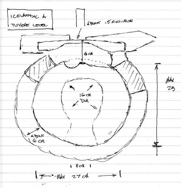
| Drawing of the excavation of the slag bowl | Measurements of the tuyere area and stone slab. |