As was mentioned earlier, the DARC fall smelt was originally intended to follow
on the development of an Icelandic style smelter.
On Friday, Darrell, Neil Peterson and Ken Cook worked on preparing the site
and building the furnace. After a fairly wide ranging discussion, it was decided
to work towards two experimental objectives:
1) Running a smelt with lower volumes of air.
2) Build the furnace using a stone slab construction method.
The stone slab construction was an extension of the Thanksgiving smelt, which
had the front section of the smelter made of stone. It also was a return to
our very first group smelt (in spring 2002). The material on hand were relatively
thin and randomly shaped pieces of mica schist. Despite some concerns about
how water can create some potentially explosive effects on this stone when it
is subjected to high temperatures, the material once again stood up extremely
well.
The shape and proportions of the furnace was largely the result of the irregular
shapes we had on hand. The overall height of the structure was also limited
by the amount of stone available. Ken undertook most of the construction work,
fitting the various slabs together as best he could. Considerable attention
was focused on the lower section and the front above tuyere level. The gaps
between the slabs was filled with prepared clay cobb and sealed using wet waste
clay. Once again the advantages of the straw fill in the cobb was obvious over
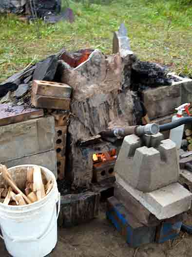
the course of the smelt. The finished smelter actually most closely resembles
the construction suggested for L'Anse aux Meadows.
The finished furnace was deemed to be the ugliest one we had ever constructed!
A large tap arch was blocked out by a nicely shaped stone. It was decided to
use a bottom extraction method for this smelt. This resulted in a rather large
lower section to the furnace, so a base level of charcoal fines was established.
With the height of the tuyere elevated above ground level, but the total height
of the furnace about the standard, the effective shaft height above the tuyere
was reduced.
Another wrinkle on the construction was a ledge of stone from the piece used
to span over the tap arch. The tuyere was positioned so that it came just to
the inner lip of this stone. In effect this placed the tip of the tuyere about
6 - 7 in from the line of the smelter interior wall.
Chamber size at Tuyere : 25 cm (front to back) x 35 cm (side to side)
Total furnace Height : 70 cm (random)
Shaft Height above Tuyere : 40 cm (minimum)
Height of Tuyere above base : 18 cm
Tuyere angle : starts at 26 down, latter shifted to 10 down
Tuyere size : standard 2.6 cm ID steel pipe
|
|
|
|
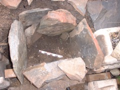
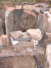
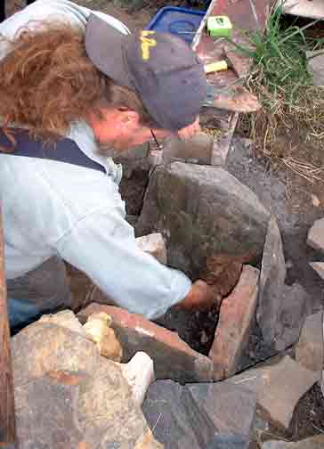
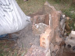
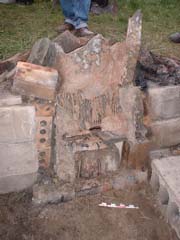
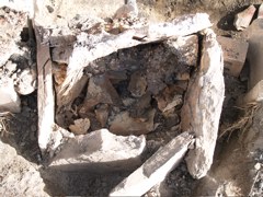
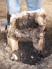
| First layer of stone slabs roughly placed. (gap for blow hole at bottom) | From the front, showing block at tap arch | Ken applying clay to seal gaps in the stones | With the front bellows plate stone in place (to the top) |
|
|
|
|
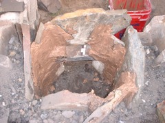
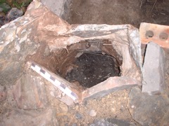
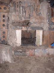
| Second layer of stones in place, backfill of ash / sand / slag mix | Front view of the smelter completed | View down the inside, with the charcoal fines base in place | View to the interior with tap arch block removed |
It was expected that the lower air volumes would greatly extend the time required
for the smelt. Although better intentions were made, the pre-heat was started
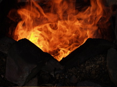
at our normal 9 AM, with primary smelt sequence started a bit after 10 AM. As
normal, pre-heat was using wood splints, passive at the start and for the last
15 minutes or so using gentle air.
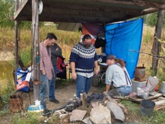
For this smelt, Neil was the iron master, with Ken working as lead hand. Darrell
started the recording, with Ron Ross managing the latter half of this task.
It was decided to seed the smelt using the poorer quality Virginia Rock ore
gathered last year by Darrel and Vandy. Although this material has proved to
have too low an iron content, it was hoped that it would compensate for the
lack of slag seen with earlier uses of the hematite grit. It was also expected
that considerably less slag would be available inside this smelt with the use
of stone instead of clay for the wall materials. In the end it proved we were
overly conservative, and production of a suitable volume of slag would prove
a problem.
With the lower consumption rates expected as a result of the lower air volume,
it was also decided to limit the total amount of ore added. It was expected
that this would only allow for the formation of a small bloom. The air volume
used over this smelt was about 400 litres per minute - compared to the usual
rate employed in past successful smelts at closer to 800 plus LPM. As was expected,
the lower air greatly extended the time between additions of the standard 10
litre charcoal measure, which increased from a normal 8 minute average to closer
to 22 minutes. The construction of the furnace had reduced the height of the
reaction column from our normal 55 - 60 cm to closer to 40 cm. Still the theoretical
'drop time' for any individual particle of ore had been extended from a normal
25 - 30 minutes to double that - closer to 60 - 70 minutes. This was expected
to produce problems in carbon control with the fine particles of the hematite
grit.
A secondary concern was the amount of penetration of air into the body of the
smelter, again an expected effect of the lower volumes. Several times during
the smelt, the depth of the heated zone was measured at tuyere level, This was
done by the simple process of inserting a 3/8 diameter mild steel rod held horizontal
to the ground through the blow hole. After about two minutes the rod was pulled
out, and the colour of the rod used as a simple measure of heat. The rear 1/3
to 1/4 of the rod did not show any visible colour, indicating that the area
of the furnace furthest from the tuyere had to be below 600 C. It was hoped
that additions of ore would none the less drift towards the ignition area above
the tuyere regardless.
Over the course of the smelt, the following totals were recorded:
Ore : 12.3 KG (10 kg hematite grit / 2.3 Virginia rock)
Charcoal : 170 litres + 6 kg ungraded fuel at start
Time : Main sequence = 6 hours
Generally the slower consumption rate lead to a much less frantic smelt sequence.
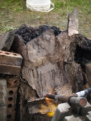
It was obvious fairly early on that less slag was being produced. Although the
furnace had been constructed as an 'incontinent' type, little slag was ever
observed flowing from the slag bowl (even after the tap arch was opened latter
in the smelt).
Neil undertook the extraction, and was able to grab almost the entire slag mass
as one piece. There was little liquid present, and not much remained inside
the furnace (generally both bad signs). Kevin Jarbeau and Ken worked the surface
quite lightly with the hammers. Almost immediately, the majority of the mass
split away, obviously only slag. The material remaining was extremely granular
and poorly sintered. Even under gentle strokes of the large hammers, it quickly
broke into a number of golf ball size pieces. Although we had hoped for a least
a small well consolidated bloom, it was clear our product was too fragile to
work.
 |
 |
 |
 |
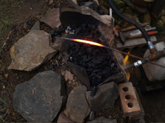
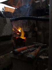
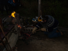
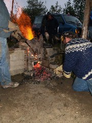
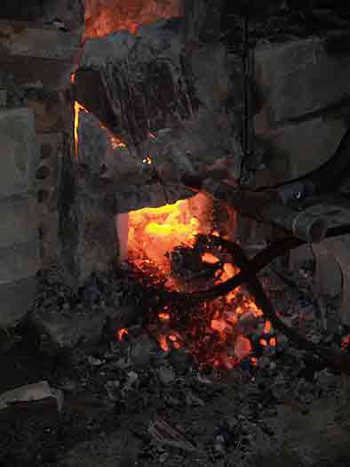
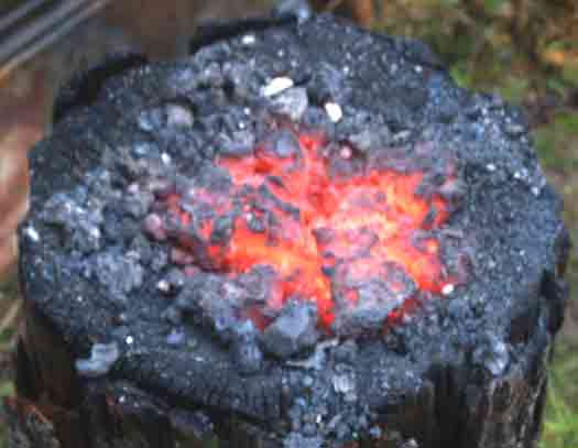
| The primary team- Neil (C) and Ken (R) | Set up for smelt at start of pre-heat phase | Latter in the pre-heat - showing typical carbon rich (reduction) flames | Start of the main sequence with addition of rough charcoal and air blast |
 |
 |
 |
|
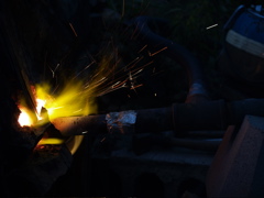
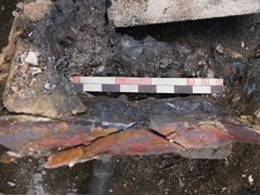
| Steel rod used to judge internal ignition zone, note only 2/3 is heated | Lower view at tuyere - see amount of blow black of air | Tuyere is lowered because of 'burning iron' sparks seen at blow hole | At start of burn down - note heat effects on front stone slab |
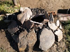
 |
 |
 |
 |
| Neil starts extraction by raking away lower charcoal fines | Attempting to move liquid slag below the slag bowl | Lower edge of slag bowl pulled free, exposing 'mother' and possible bloom | After just a few strokes with the hammer. Crumbly fragments of metal |
For the Experimental Field Data - continue HERE.
The next day the cold smelter was excavated, with a good photographic record
made and representative samples collected. All the slag was collected, and the
area was cleaned with the large magnet. The results of this work:
Weight of Slag : 3.5 KG
Weight of Reduced Ore (but poorly or not sintered) : 3 KG
Weight of 'Bloom' (fragments) : 2 KG
Although the general opinion on the day was that the product of the smelt was
in fact a high carbon cast iron, I personally had some doubts. In past uses
of the hematite grit as an ore material, the results even with high air volumes
always had a granular texture and a high carbon content. On Tuesday I attempted
to work one of the denser fragments inside the coal forge. Knowing how fragile
this granular material would be, the roughly goose egg piece was brought close
to a welding heat and very gently worked with a wooden mallet. Even under the
lightest of strokes it was not possible to do much more than just push the grains
a bit closer together. I was not able to actually forge the material into any
kind of solid piece. The end result was just a larger pile of smaller fragments.
One piece (about 3 cm wide and about .5 thick) was compressed enough to have
a noticeably flat surface, this was taken to the grinder for a spark test. The
sparks produced were like those seen from a piece of high carbon tool steel
(in the range of 1 % plus carbon content). It may prove possible to forge weld
the fragments between two other slabs, but I was unable to work the material
as it exists at this point.
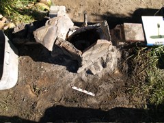
 |
 |
 |
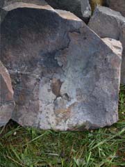 |
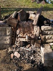
| Smelter remains next morning | Top area of the smelter remains | With earth packing and supporting stones removed | One of the upper rear slabs after the smelt - note little physical change |
 |
 |
 |
 |
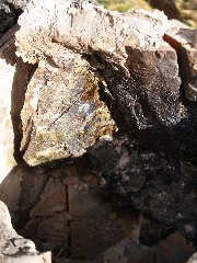
| Side view of inner surface - slag attached to front surfaces (R) | Exposing the inner slag bowl remains and lower set of slabs | Slag attached to inner surface above and around tuyere area (middle) | Top View of tuyere area with front slab removed - note slag and colour |
 |
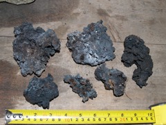 |
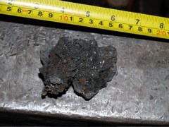 |
|
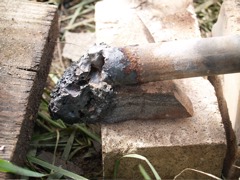
| Solidified slag attached to pipe tuyere | Larger 'bloom' fragments | Piece selected for consolidation test |
Conclusions:
1) The construction method using stone slabs with clay cobb sealing the joints
is certainly viable. It is unlikely that the mica schist material would withstand
a second firing without heavy replacement of the material at the normal hot
zone above the tuyere. The stone in this area exhibits both considerable erosion
and also a thick deposit of slag. Both of these effects should remain clearly
visible in archaeological remains of this type.
2) The use of lower volume air requires considerable further experimentation
to develop a truly successful sequence. As has been clearly demonstrated with
both our earlier smelts and those of other experimenters - there is a (poorly
understood) relationship between ore type and purity, smelter material and design,
fuel preparation, and physical sequence. Those attempting smelts with low air
volumes have great difficulty (if able at all) in producing large and well consolidated
blooms.
3) In retrospect, it is most likely that both the content and the fine particle
size of the hematite grit renders it quite unsuitable for use in any kind of
low slag producing smelter. The extremely low silica content of the ore means
that the formation of slag must come almost exclusively from the melting of
the smelter walls. Although good results have been attained with this material
in past smelts, this has always been inside those furnaces that have suffered
considerable internal erosion.