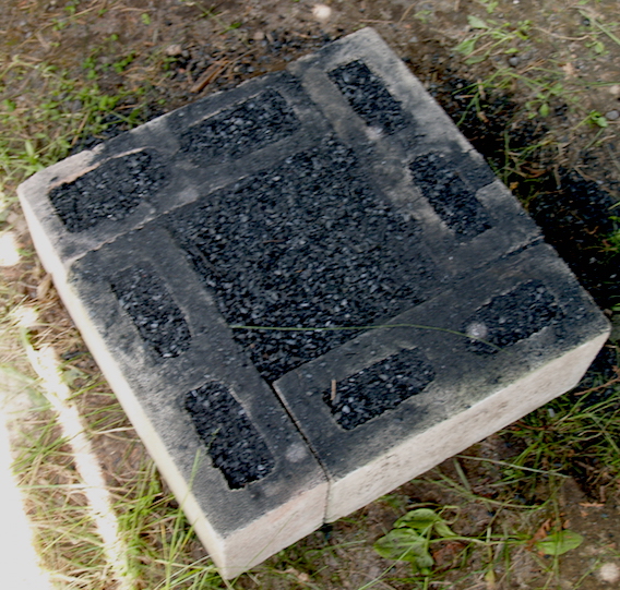
The 'Vinland' clay is the darker material
LAM, Lower & Longer :
June 25, 2022
Reduced air Volume
'Vinland' clay test
For the first smelt of 2022, a new furnace was constructed, a
slightly smaller diameter 'Norse Short Shaft' set on a plinth. The
smelt was conducted applying an air volume based on the
measurements from the October
2021 'Wind' testing. The secondary experiment was the
inclusion of a patch of furnace wall made up of materials gathered
at L'Anse aux Meadows, Newfoundland (close to the Norse 'Vinland'
archaeological site).
Part One - The Smelt :
The furnace constructed for these experiments was the long proven
’Short
Shaft’ type. (1) In this case the furnace structure was
placed on a rectangular plinth formed from 'half thick' concrete
blocks, centre filled with charcoal fines. The blocks stood 18 cm
tall and created an internal square at roughly 26 cm.
The majority of the clay walls were constructed of EPK powdered
clay, course sand, and dry shredded horse manure (rough thirds by
volume) again a standard mixture. Individual fist sized ‘bricks’
were placed against an internal metal form, resulting in a 25 cm
internal diameter. The walls tapered from 6-7 cm at the base to 4
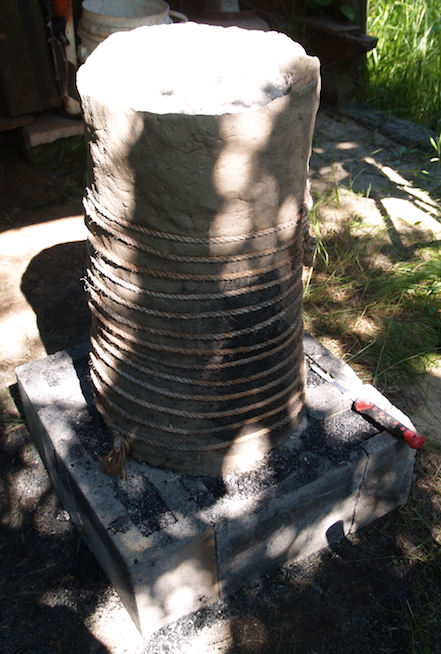
cm at the top. During the build, the exterior was wrapped in rope
to reduce sagging. To both support the structure and promote
drying, the interior was filled with a mixture of sand and wood
ash.
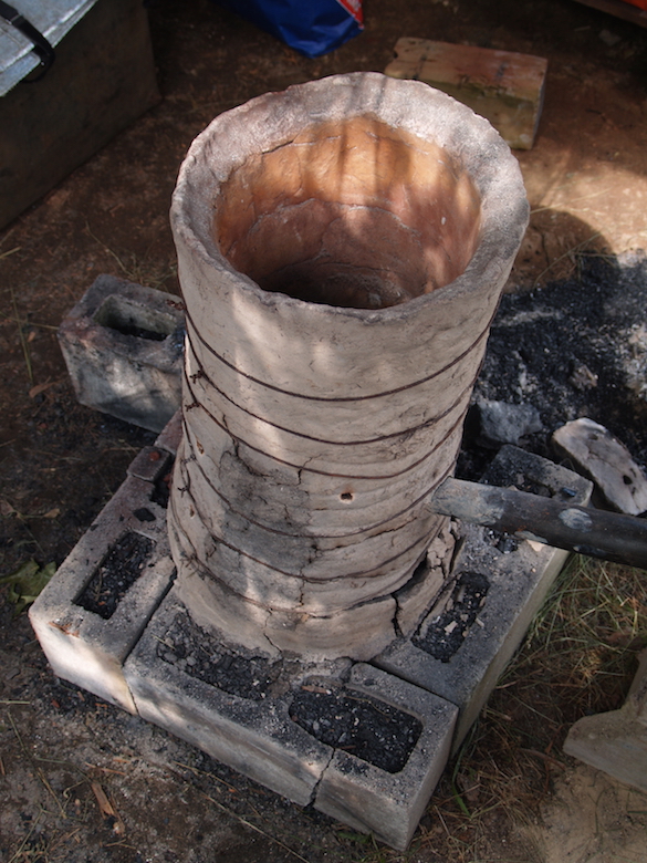
|
|
| Limestone blocks laid out for the plinth | Completed build, rope
re-enforcing The 'Vinland' clay is the darker material |
The initial construction would result in walls built to an
average of 60 cm height (varied 59 - 62 cm). The scheduling was
collapsed, with the build undertaken over the afternoon the day
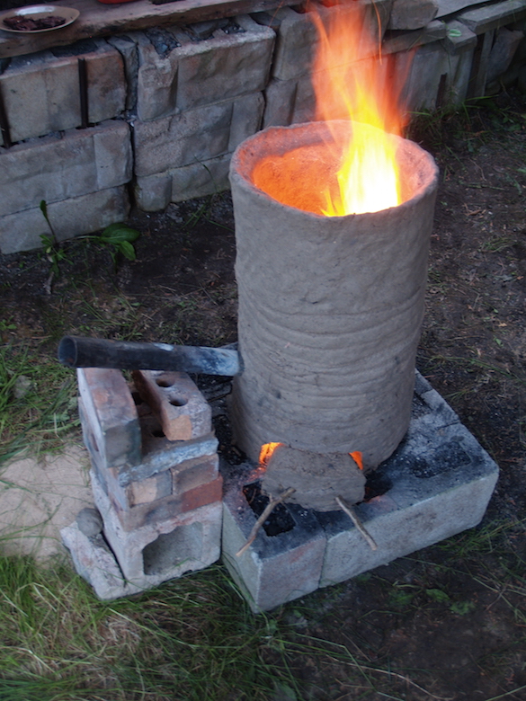
before the smelt, and initial drying fire that same evening. This
would lead to more than typical cracking in the furnace wall,
primarily running along the joints between the individually
applied 'bricks'.
 |
 |
 |
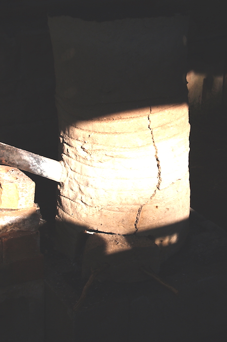
| During drying fire - tuyere set | After drying - major crack above extraction arch | Vertical crack does not extend through interior |
Because of the number of smaller cracks (most not extending into
the interior) it was decided to place a series of loops of soft
iron wire around the body of the furnace, placed about every 10
cm.
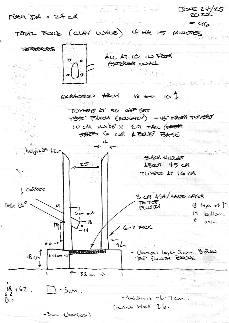
The tuyere was the heavy forged copper proven over many previous
smelts. It was set as has been shown effective :
 |
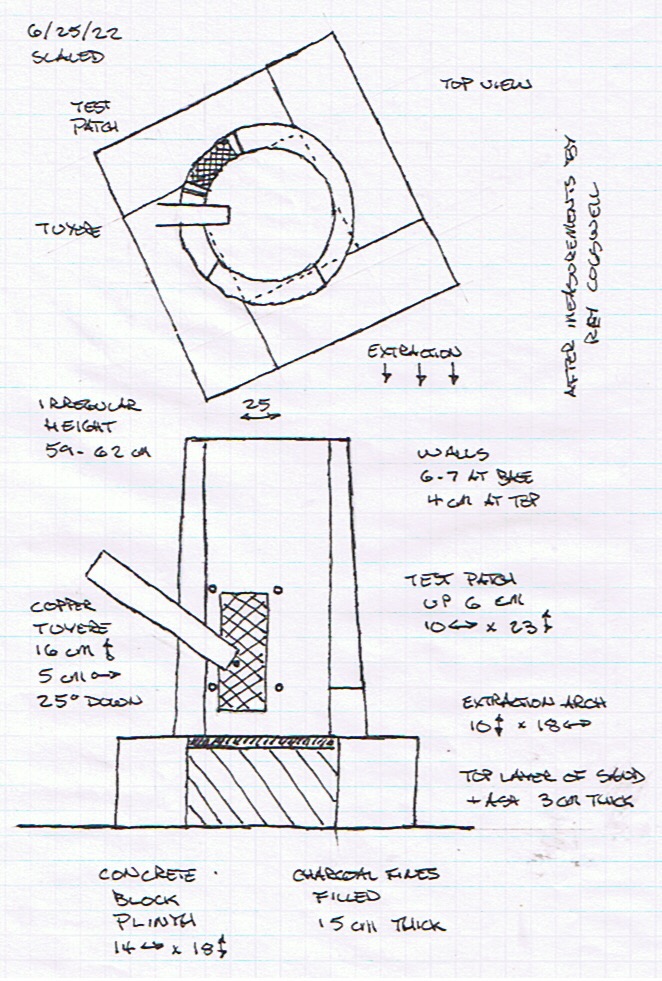 |
| Rough field drawing by Rey Cogswell (with additions) | Converted scale drawing |
 |
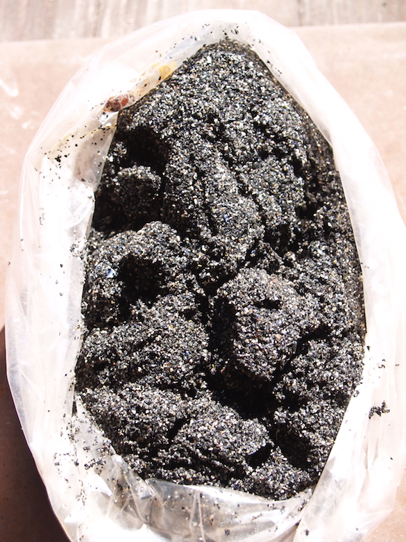 |
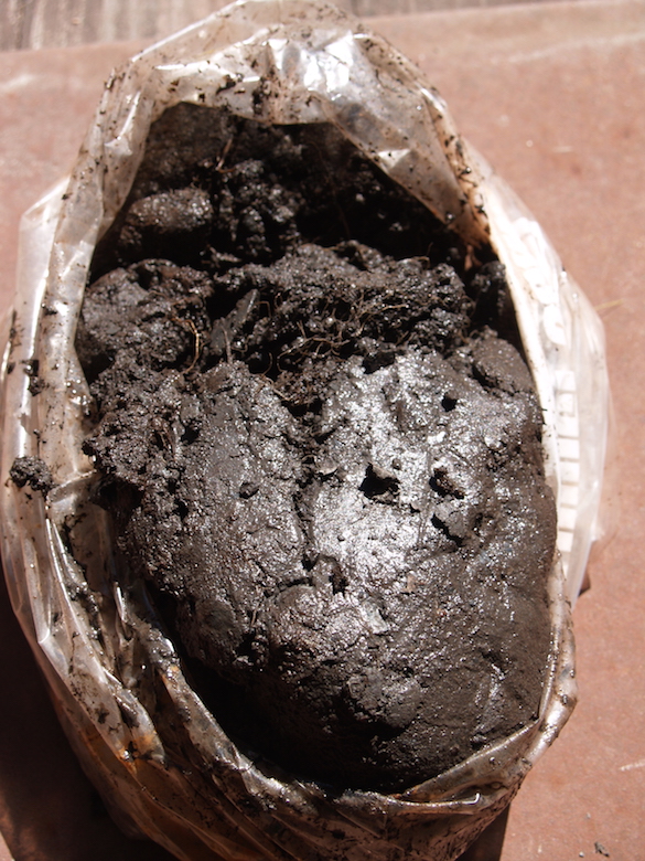
| Raw clay from the Norstead bank |
Basalt sand from the Norstead beach
|
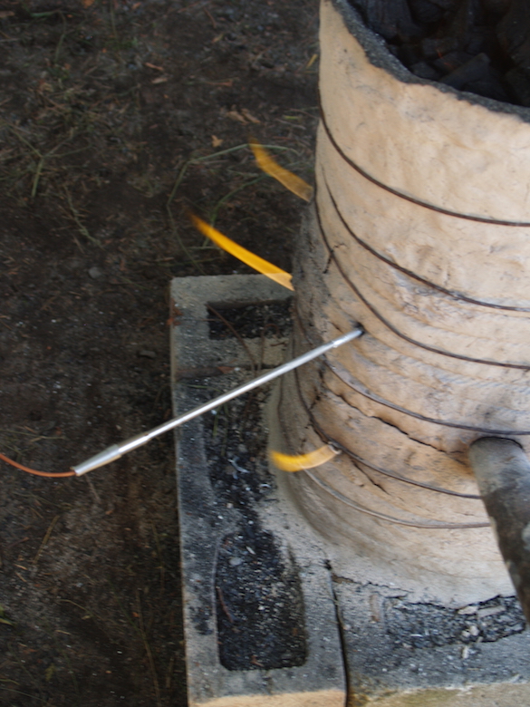 |
| Using thermocouple, time point 1035 |
 |
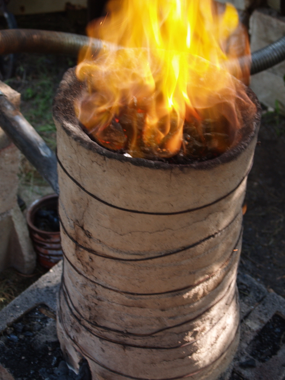 |
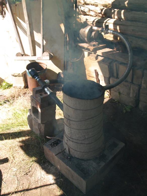
 |
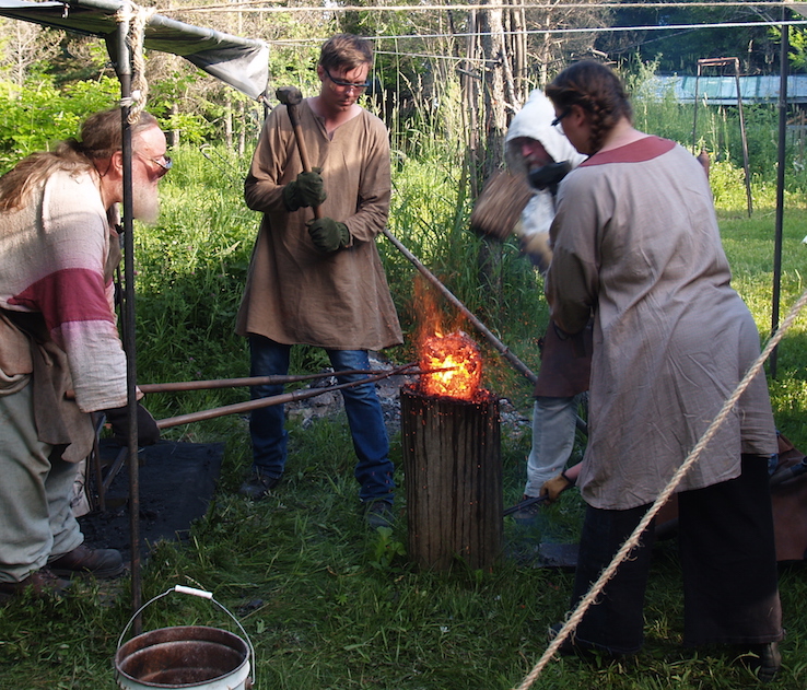
| Air supply, blower with gate to rear | Part way through main sequence | Ore addition (at later 3kg charge point) |
Team :
Darrell Markewitz = (furnace construction) smelt master
Neil Peterson = records, ore measure and compaction
Maxim Fedetsov = charcoal, charging and compaction
Rey Cogswell = charcoal and extraction
Isabelle Wigglesworth = charcoal and compaction
Richard Schweitzer = compaction
Sequence :
The sequence data is available here.
Air :
The standard air supply has been provided by a compression styled
high volume electric blower (purchased in 2008 as US Navy
surplus). This unit is rated to 1400 LpM, considerably more than
required for past smelts in the typical 25 - 30 cm ID furnaces.
During the 2021 'Wind & Weathering' smelt, a series of air
volume measurements were undertaken, using a more accurate Omega
HHF 1000 flow meter, providing continuous output linked to a lap
top for recording. Part of that experiment included measuring air
delivery using the previously constructed 'smelt bellows', over
three different production cycles, each with turns taken by three
different operators. (3) Overall, the average produced was 520 LpM
(based on a stroke count of 60 per minute).
For that reason, the output of the electric blower was reduced to
approximately 500 LpM, as indicated by the scribed lines on the
blast gate. These were marked a number of years and many
experiments ago, lines which were at best rough indications of the
values. Comparison of the marks against actual flow volumes as
measured by the accurate meter in 10 / 2021 suggested that the
actual delivered air was roughly 85 % less than the plate marks.
Unfortunately a less accurate (and somewhat problematic)
instrument was brought for this experiment, rather than the new
(and accurate) Omega unit.
Taken together, the actual air volume employed is estimated to
425 LpM (very roughly!). Working from the well proven
guidelines for air volume against internal area documented by
Sauder and Williams, the 'ideal' air volume for a 25 cm ID furnace
would be between 590 to 880 LpM.
The primary impact of this reduction in delivered volume was seen
in the considerable increase in charcoal consumption rates, at an
average of 24 minutes per 'standard bucket' of 1.8 kg. / time
per 1 kg at just over 13 minutes.
Temperatures :
Because the expectation was that the interior of the furnace
might approach as high as 1350 C, the probe was removed at roughly
1270 + C, while numbers were still increasing. At one point
distraction meant the probe was left in place too long, and the
stainless steel shell on the probe actually melted off, suggesting
the temperature at that point and location had well exceeded the
rated temperature of the thermocouple of 1330 C. The first set of
measurements were made only 35 minutes after the first addition of
charcoal, it is clear this furnace quickly ran up to suitable
operating temperatures. The 11:25 (clock) time, about an hour
after first charcoal, was just before the first addition of the
Barton's Run material. The 12:24 time just before the first
addition of ore analog.
| TIME (clock) |
10:35 |
11:25 |
12:24 |
| POSITION |
|||
| bottom front |
1270 + |
1275 + |
1150 |
| top front |
1020 |
1275 + |
overload |
| bottom rear |
1270 + |
1275 + |
1270 + |
| top rear |
960 |
1245 |
1150 |
Table A : Charting the interior temperatures
Extraction :
The furnace had been constructed on a block plinth, specifically
to make extraction easier.
The clay door to the extraction arch was pried loose, and the two
front blocks swung open. This allowed for the bulk of the lower
layer of charcoal fines to be raked clear. Initial probing
indicated that the slag bowl had filled the bottom of the furnace,
and so was attached completely to the walls. With space below, the
log 'thumper' was used to quickly beak the entire slag bowl down
and free. Although a quick process, this did result in a
considerably larger mass than normal to pull and carry over to the
stump for compaction.
| |
| Video
Sequence of the full consolidation process, by Anita Herbert (used with permission) |
 |
 |
| Starting compaction, slag bowl still attached | Part way through compaction, encasing slag obvious |
A considerable surprise was the size of the final bloom at 7
kg. The material remained fairly spongy in consistency,
likely with some internal slag. The produced yield was 28 %,
considerably higher than expected based on past experience.
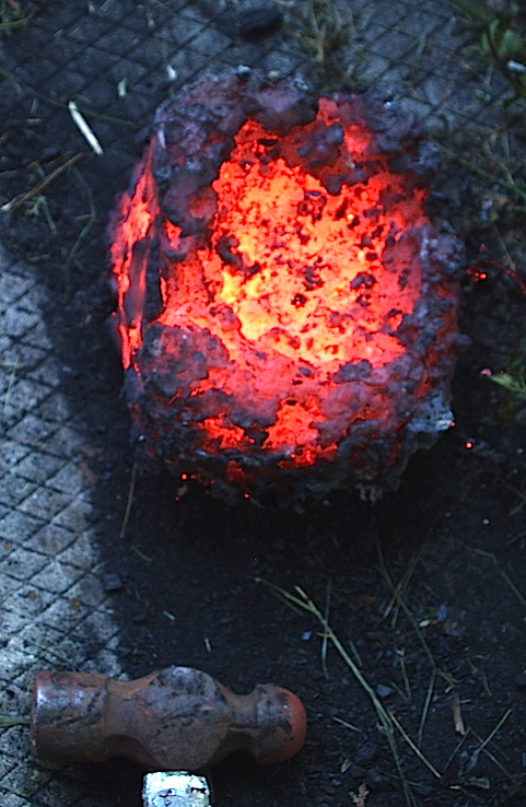 |
| Final bloom, top surface, likely tuyere to SE side |
The image above was taken at the end of the consolidation
hammering. (Beware the extra brightness applied by the camera, the
actual heat colours were medium orange to dull red) The film of
slag still attached are clear as the dark areas over the hotter
metal core. The upper surface of the bloom had a distinctive
hollow in the centre. This is sure to have been caused from both
the slag bowl and the collected bloom sitting too high in the
furnace, resulting in the air blast cutting into the top surface
and eroding it. This all is likely an effect of the lower than
ideal air flow, which did not penetrate as deeply into the bottom
of the furnace. The effect might have been reduced if some of the
fines had been scraped out, allowing the developing bowl to settle
downwards midway through the smelt. (Note that this suggests that
with better control, the bloom might actually have been larger!)
Part Two B - 'Vinland' Clay
Did the 'Vinland' Clay survive use as a wall material in a
full iron smelting sequence?
The answer is a 'qualified' yes.
During build and drying sequence, the Vinland clay proved a bit difficult to blend uniformly to the standard EPK mixture. Perhaps predictably, the Vinland clay mix was found to contract at a different rate, producing a crack that ran along it's margins. This was repaired simply enough by just adding additional clay into those cracks. There was no actual failure of the Vinland material, in terms of cracks venting furnace gasses or burning through during the smelt.
 |
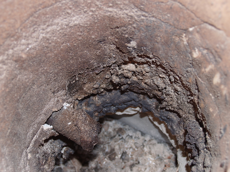 |
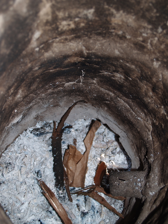
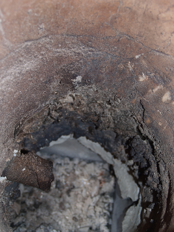
| interior, showing entire 'Vinland' clay area | detail, lower portion of 'Vinland' clay area |
When the interior of the furnace was examined the following day,
it was clear that the Vinland clay had suffered significantly more
heat erosion effects, basically starting to melt. In the images
above, it should be noted that the hottest part of the furnace is
located in a rough oval around the tuyere, typically extending 10
cm to either side and bellow, plus to 15 cm above. In the detail
image above, there is a clear difference between the appearance of
the EPK (virtually no effect) compared to the Vinland clay at the
same height. This despite the fact that the Vinland test material
was positioned just beyond the normal 'hot spot'.
When the exterior surface of the furnace was examined however,
the results of furnace use were different.
 |
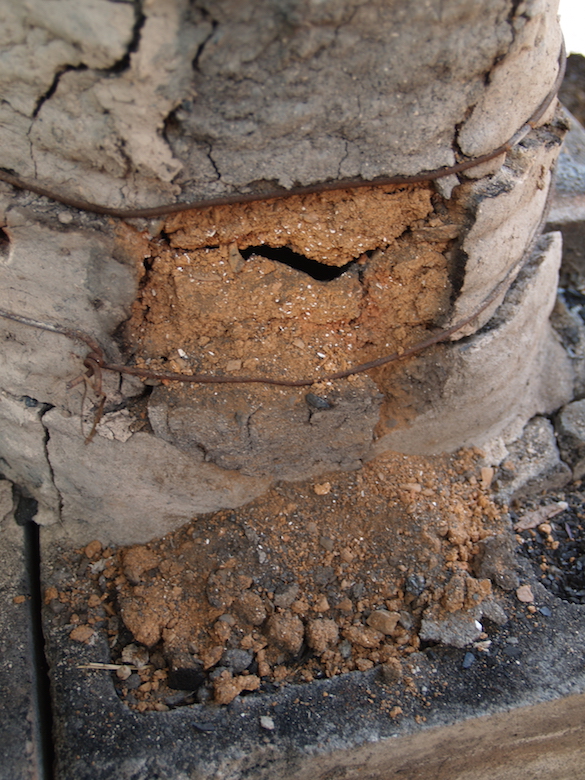 |
| Vinland test patch after
firing |
After handling of surface |
At first glance, the Vinland patch looked to be in about the same
condition as the rest of the furnace walls. there was a clear deep
crack running around the whole boundary of the patch, but this was
not considered unexpected, as differential shrinking had already
shown these cracks. The surprise was when the test material was
examined more closely.
| June 2022 |
October
2021 |
|
| Ore Amount |
24.5 kg |
24.3 kg |
| Bloom |
7 kg |
7.6 kg |
| Yield |
28 % |
31 % |
| Furnace ID (at tuyere) |
25 |
28 |
| Air Volume |
425 LpM (estimated) |
750 LpM (average) |
| Air per cm2 (at tuyere) |
0.86 LpM |
1.22 LpM |
| burn rate (average) |
13 M/kg |
8 M/kg |
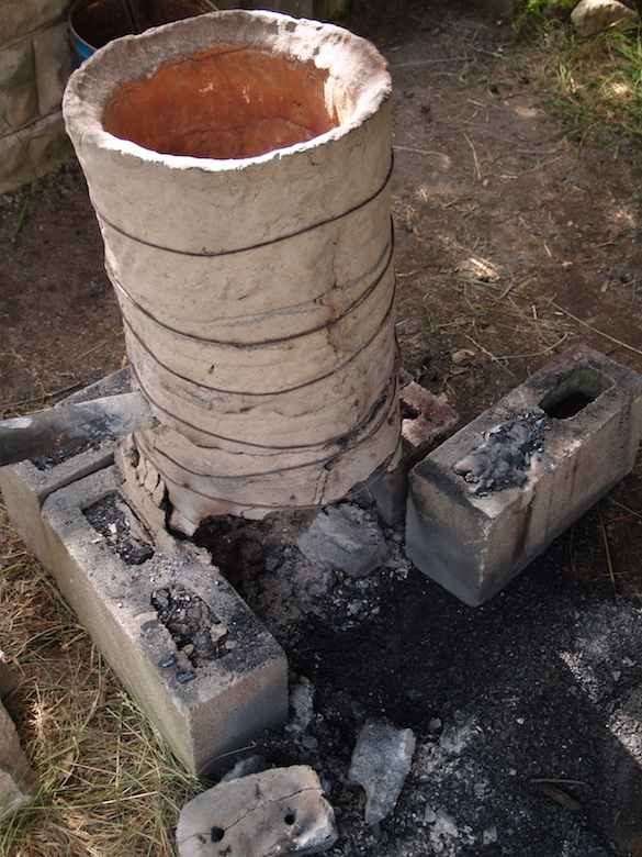 |
| Following morning, extraction side. Note
breaks along 'brick' seams |
a) Building an air control unit that uses a mechanically driven sliding plate in place of the fixed blast gate set downstream of the electric blower. By using contoured plates, the pulsing nature of human powered strokes could be mimicked. Although long considered, the mechanics have proven daunting.By far the simplest approach would be simply to return to using the actual 'smelting' bellows currently on hand. The primary draw back there is the requirement for the labour pool required just to operate the bellows over the 6 - 8 hours estimated for a full smelt. (The average age of the current smelting team is into their mid 50's!)
b) Repeat the experiment using a furnace with a significantly larger internal diameter. Ideally this after a general survey of the existing Viking Age smelting furnaces with an eye to approaching an average historic size. This may prove problematic however, and there are no existing artifact bellows, or even any clear indication of what sizes (so volumes) may have been actually used.
Unless otherwise indicated :
All text and photographs © Darrell Markewitz,
the Wareham Forge.