Work Dynamic Test
Icelandic / Hals - Bellows Plate with Blow Hole

October 12, 2008


For a better understanding of the experimental sequence involved, readers are referred to the discussion of the evidence from Hals, Iceland - 'Working towards a Viking Age Icelandic Smelter'.

Hals Reconstruction
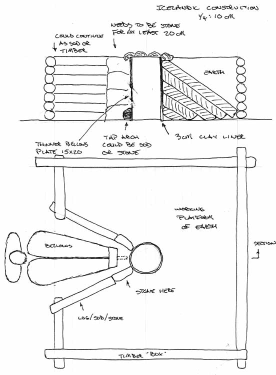
The proposed reconstruction of the Hals smelter.
Conversion for the Work Dynamic Test:
Plan View
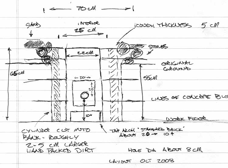
Front View showing some important theoretical measurements.
Plan View showing construction details and working areas.
Cross Section showing bellows and front working area.


Experimental Variables:

1) Overall set up is a totally earth surrounded smelter at the end of a slot - with the layout similar to those at Hals
2) Use a medium walled clay cobb furnace structure.
3) Block in the location of the hand bellows, but use the electric blower for air
A) Use a bellows plate construction
B) Use blow tube arrangement for the tuyere (which can quickly be modified to our normal insert tuyere if required.
This suggests one minor (number 1) plus two major changes (A / B). There is some limited experience with A / B, and 1 is more a modified work dynamic than an actual major change.
- The set up of the furnace with only a small tap arch down a slot certainly leads to a top extraction.
- Ore should be a known and proven type.
- The aim is for a 3 - 5 kg bloom. (Hals size in range of 15 x 15 x 10 cm)


Preparing the Work Site:
Existing Arrangement
Starting Work
Align Blocks
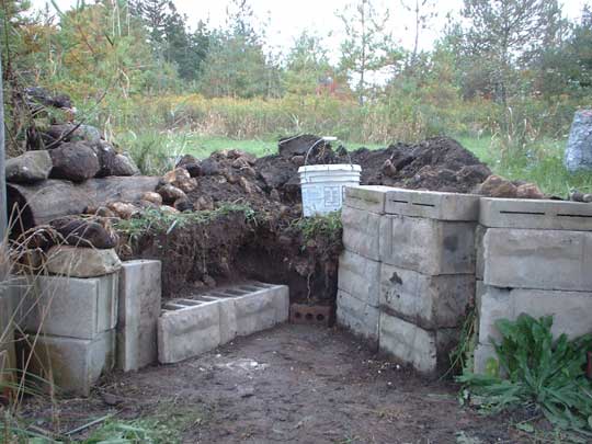
A simple plan view of the initial situation with layout of the Icelandic smelter indicated.
Photo of the same view after the rail ties had been placed.
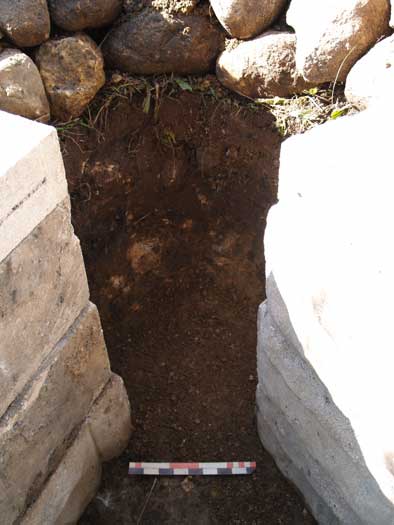
With the working slot lined with concrete blocks.

When the original working area in Wareham was laid out, it was designed to allow for two smelters to be installed side by side. The earth bank that defines the western edge of the working area was retained by a line of concrete blocks, which could be easily moved to make alterations. Two of the rail road ties were used these to block in the 2 m x 2m overall size indicated at Hals. On the actual above ground sod construction, this would be a log crib. With the length of the ties actually a bit more than required (and lots of stones!) the rear dimension was set using a row of rocks. By removing three stacks of the retaining wall blocks, there is about the correct opening for the front V of a working area leading back to the smelter front wall. (The final position of the smelter shaft is indicated by the white pail in the photographs.) Measuring from the current work surface to the tops of the two rail ties, establishes about the correct height proposed for the Icelandic construction.
After about 6 hours work, the bank was cut back and concrete blocks have been used to secure the walls to create the V shape work area. The space between the V of the block walls is the length of a standard brick (about 25 cm). As usual for Wareham, the larger rocks (about head size) seen on the left were of course just sticking out an inch or so from the digging lines!

Constructing the Smelter:

The next task was to first cut a rough cylinder into the earth bank, then build the clay shaft of the furnace. As with past construction, the clay cobb was composed of commercial powdered potter's clay mixed with about 50 % by volume of chopped straw, cut to 5 - 8 cm lengths. A space for the tap arch was determined by framing it with a standard brick about (20 cm long x 10 high) As each course of clay cobb was built up, loose earth was hand packed into the irregular space between the exterior wall surface and the cut earth. To balance this inward force and stabilize the thinner walls, course sand was used to fill the interior space to the identical level. It was also hoped that the sand would help to wick off some of the moisture from the wet clay. As the cylinder reached the level of the working platform (about 65 cm total height) a ring of stones was placed to support the upper edge.
Showing the rough cylinder cut into the earth bank. Again the rock filled soil at Wareham made getting a clean edge and correct size and shape impossible.
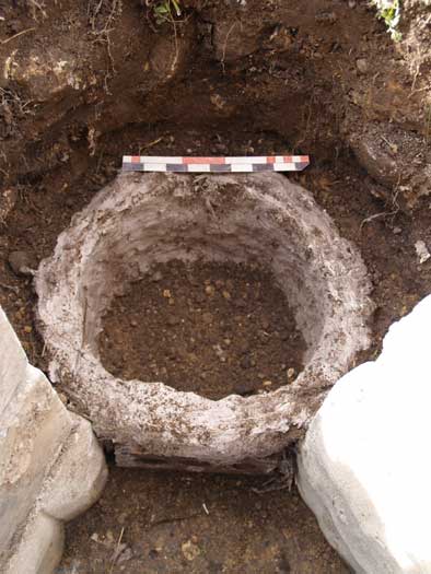
The first course of clay cobb laid in place. The approximate wall thickness was kept to 5 cm. The brick used to frame in the tap arch can bee seen.
At the completion of the third course. The sand used to stabilize the interior shape can be seen.
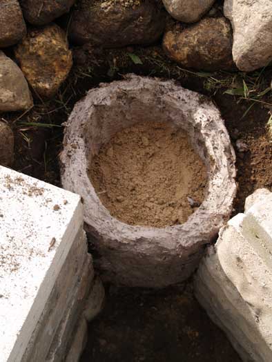
The finished cylinder, within its ring of stones.

The last step in completing the working platform was to top off that surface with about 5 cm of clean course sand.
In the image (far right above) can also be seen the still wet bellows plate. This was made up of a 50 / 50 mix of powdered clay and shredded, dry horse manure. Replacing the straw with manure gives a finer texture to the finished plate. The plate measured 20 cm wide by 25 cm tall, overall 3 cm thick. Into the later part of the drying process described below, the steel plate that the finished tile can be seen on was placed over the mouth of the smelter to bake the clay dry.
The structure was left to stabilize for a few hours. The sand inside was then scooped out (by hand). As the lower area was reached, the brick supporting the tap arch was carefully pulled out, allowing the balance of the sand to be cleared. This was then replaced, set so the holes through its center would lead into the shaft. At this point a very gentle split wood fire was started inside the shaft. This process of adding a handful of splits at a time would continue for several hours. At the end of the evening, a metal cover was placed on the open top of the shaft so the coals created would slowly bake dry the smelter over night.
The next morning the whole smelter shaft was found to be still warm to the touch, and was baked dry and hard. A layer of ash and fragments of unburned charcoal was found to a depth even with the tap arch. A dry wall saw was used to lay out a rectangle the same size as the bellows plate, and then that portion of the smelter wall was cut away. The supporting brick was removed from the tap arch so the ash from the drying fire could be scooped out.
The bellows plate was also dry and hard, and was found to have curled up slightly at its edges (from the aggressive drying over the fire). The plate was trimmed slightly to fit, then installed into the smelter. It was positioned so that it would sit flush with the inside smelter surface (thus slightly recessed on the outer face). Fresh clay was used to mortar in the plate to the smelter walls. There was some concern at that time because of the difference between the consistency between the dry surfaces and this fresh clay. It was expected that considerable shrinking and eventual peeling away of the joints might lead to problems latter on in the firing sequence. (Which did prove to be the case.)
Last a hole was cut into the bellows plate. The position was determined from the earlier layout drawings, the centre roughly 25 cm above the base line. The size of this hole was 8 cm, sized to leave 1.5 cm clearance around the exterior diameter (at 5 cm) of the standard ceramic tubes used for tuyeres.
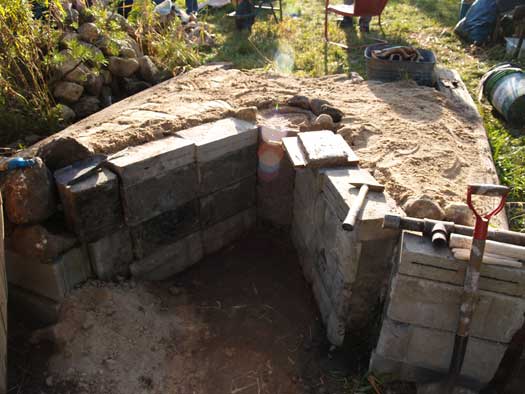
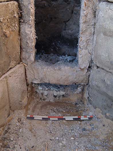
With hole for plate cut, before removing the ashes from the drying fire.
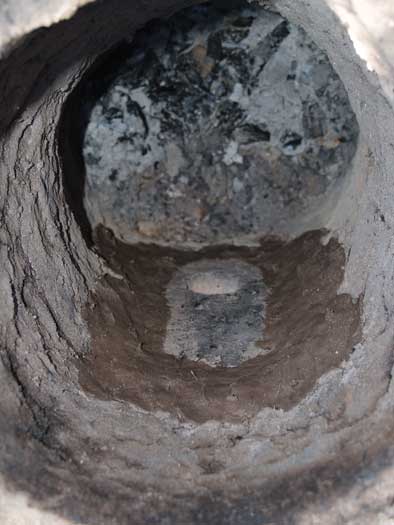
Down the inside of the smelter with the bellows plate installed.
A view of the exterior of the smelter with bellows plate installed.


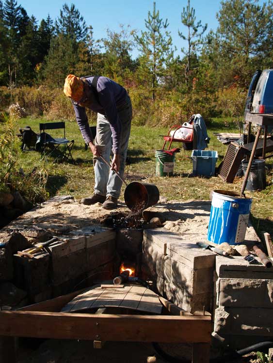
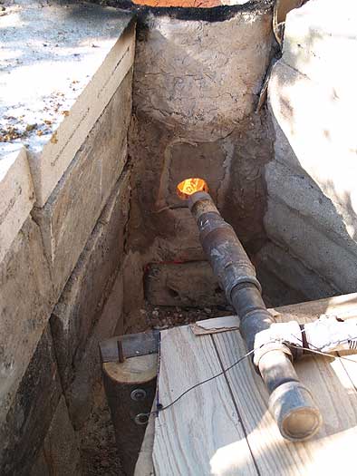
Setting Up for the Smelt:

As one of the objectives was to determine the work pattern (and problems) with the layout including a human powered bellows, the space for this equipment was determined by positioning the frame required to support a Norse style double bellows of suitable size. The space was then simulated with a full sized cut out in the same location. The standard electric blower was then use to provide the required air, with a flexible pipe attached to the normal T fitting. The working end consisted of one of the commercial ceramic tube tuyeres (2.5 cm interior diameter). The measured angle on the air pipe was 15 degrees down. The gap between the tip of the air pipe and the surface of the bellows plate was established by sound (adjusting for the loudest and 'throaty-est' roar). Once this was established, the air pipe was wired into place on the wooden frame. The resulting gap was about 3 - 4 cm determined with an air flow estimated at 740 litres per minute.

The final measurements of the finished smelter.
With the new experimental double bellows in place on the frame.
Frame remains, with the standard forced air system in place.
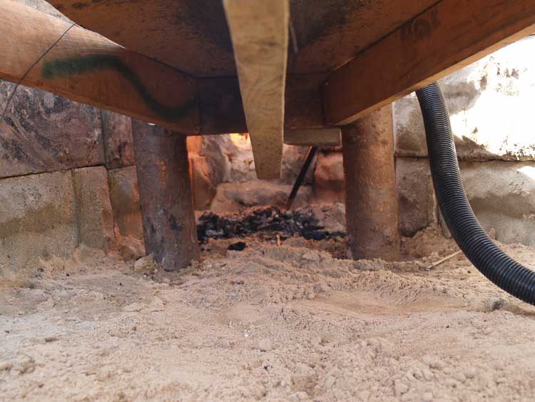
The view underneath the frame towards the tap arch.

As with past smelts, a preheat phase using split wood was applied first. This was done using natural draft for one hour and ten minutes, followed by a brief period with gentle air flow from the blower supplied. No specific base was set for the furnace, the ash and mostly consumed charcoal from the preheat phase was left in place. (The normal practice is to use a layer of charcoal fines to define a floor for the furnace at a measured distance below the tuyere.) The total preheat was one hour and 18 minutes, at this point the smelter was filled with rough charcoal and a full air blast was started. The furnace would require about 45 minutes operation to completely ignite the working column to the top.

Main Smelt Sequence:

(Go on for the Experimental Data Sheet )


At the start of main sequence the consumption rate was about 13 minutes per standard bucket (measured at 1.85 kg), so charging with ore was started.

Adding charcoal, working on top of the 'platform'.
Addition of the first ore charge.

For this smelt, it was decided to use a combination of the remaining industrial taconite plus the poor quality Virginia rock ore. The rock ore was considered to be a bit low in iron content, and so was added first to establish a working slag bowl. Additions were measured 'by the scoop', with the actual weights determined mathematically later. Larger charges were used right from the start, being 4 scoops (1.1 kg total) within each bucket of charcoal. After a total of about 8 kg of the rock ore was added, charges were switched to the much higher iron content taconite. (Both materials had been roasted and crushed to the normal 'rice to half pea' size.)
Just about the point were the switch was being made to the second ore type, problems were starting to be encountered with the function of the blow hole air system.
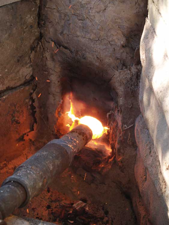
After adding about 4 kg of rock ore, showing cracking of the clay around the edges of the bellows plate (not in itself critical). After adding about 8 kg of the rock ore. The skim of glass freezing in the air blast on the top of the slag bowl is clear to see to the left. After some frantic activity - conversion to an insert style tuyere to save the smelt After the heat has returned to correct levels and the frame removed the tap arch is cleared and the furnace begins to self tap.

After the addition of roughly the first 8 kg of ore, (about 6 kg fallen to tuyere level) the top of the slag bowl could be easily seen just below the bottom edge of the blow hole. Several attempts were made to gather excess slag on to a metal rod to lower the level. This met with limited effect, largely due to limited skill and experience of the operators. A film of hardened slag could be seen developing to the left edge of the blow hole. Clearly the slag was starting on its way to blocking the air flow. Unfortunately, an especially large gather of slag slid off the rod right at the hole's mouth, completely blocking the blast. Immediately, the temperature in the whole furnace began to plummet. With some frantic activity, that slag was shoved into the centre of the furnace, and the ceramic tube was pushed through the bellows plate to convert the smelter into an insert tuyere type.
This effectively halted two of the primary objectives of the experiment (use of bellows plate and blow hole combination), but did recover the furnace temperatures back up to correct operating levels. After about 20 minutes the burning rate had returned to the 13 minutes per charge established before this disaster, and ore charges were resumed.
At this point the air pipe system was hung from an overhead support with wire so the bellows frame could be removed out the way. It was then possible to open the tap arch and clear the wood ash from underneath the slag bowl. Almost immediately, the furnace began self tapping with the typical late stage dark black, solid and fluid slag.
The charges of taconite were denser than the earlier rock ore, with 1.6 kg per bucket being added roughly every 13 minutes for the balance of the smelt (roughly 1 : 1), an additional 15 kg.
<object width="425" height="344" align="middle">
<param name="movie" value="http://www.youtube.com/v/ilZitcYyVoA&hl=en&fs=1"></param><param name="allowFullScreen" value="true"></param><param name="allowscriptaccess" value="always"></param><embed src="http://www.youtube.com/v/ilZitcYyVoA&hl=en&fs=1" height="200" align="middle" type="application/x-shockwave-flash" allowscriptaccess="always" allowfullscreen="true"></embed></object>
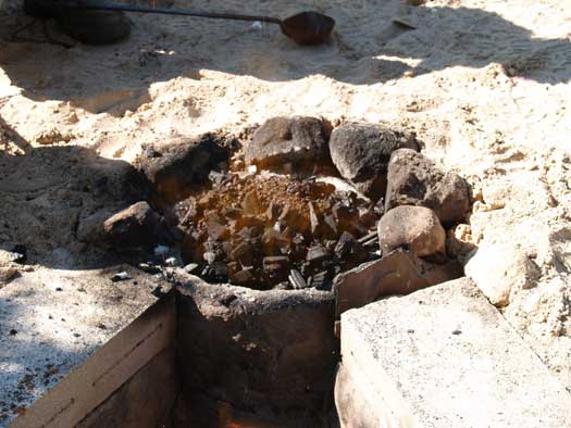
At the top of the furnace, just into the burn down phase
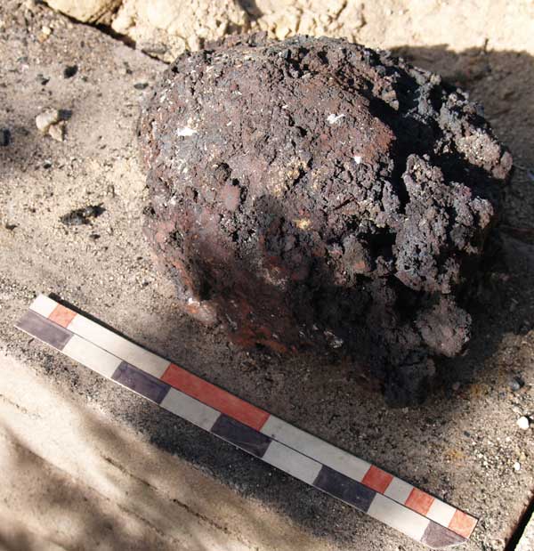
The finished bloom, after one compaction series.
A brief overview of the smelt

When the last ore was added, the remainder of a charcoal bucket was used to cover it, and the furnace taken straight into the burn down phase.
As is common, there are few images of the actual extraction phase of the smelt. In this case there was some video footage shot, which later was edited up the short YouTube sequence seen above.
The extraction started with an attempt to pull from the top. The charcoal was allowed to burn down to quite close to the top of the slag bowl. For this reason, the debris field was quite limited on the upper working platform. Neil started the extraction process, but was having some problems assessing just where the bloom had formed and for that reason (plus more limited experience) had considerable problems. The initial compaction and loosing of the bloom with the thumper in place inside the smelter was therefore not as effective as might have been desired. Through this effort, the temperature inside the furnace was dropping, and the slag mass slowly congealing. Eventually it proved necessary to switch to a bottom exaction through the tap arch. By the time the bloom was eventually pulled from the smelter, it was in fact too cold to undertake any significant consolidation. It was possible to knock free the loose 'mother' and shape it to a rough brick shape.

Smelt Totals:

Ore - 23 kg (8 kg Virginia Rock / 15 Taconite)
Charcoal - 46 kg
Time - 6 1/2 hours (plus burn down)
BLOOM - 4.9 kg
Yield - 18 %

Remains After Smelt:

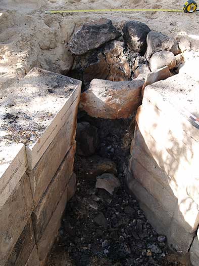
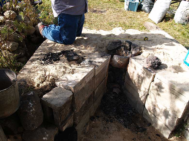
An overall view of the entire working area.
A closer view of the damage to the smelter itself.

The next morning, the tools were cleared away and a closer look was taken of our working area. The layer of clean sand that had been deposited over the upper platform and to the front of the smelter slot made assessing working patterns easier.
- There was very little debris of any kind deposited on the upper working platform. This was do partially to the more complete burn down to the top of the slag bowl than had been done in the past. This was not entirely intentional, but more a result of a longer time getting organized by a less experienced operator who started the extraction process. Less partially consumed charcoal remained to be scooped away, also leaving a higher percentage of 'slag drips' mixed in with that material (clearly seen to the left of the first image above).
- A considerable amount of material remained just in front of the smelter, inside the working slot. This tended to be small pieces of unburned charcoal, fragments of broken clay smelter lining, with smaller pieces of the slag bowl. This was the last scatter of material remaining from the eventual bottom extraction. It should be noted that our normal practice is to constantly shovel the hot piles of slag chunks and still burning fuel away and out of the working area during extraction for safety reasons. The restricted area inside the narrow slot made this even more important than normal.
- After the tap arch block was removed, there was little supporting the thin and fragile exposed front wall of the smelter. As soon as any force was applied to the slag mass, the narrow arch of wall material between the tap arch and the bellows plate broke away. This caused the plate itself to come free, pretty much in one piece. In the right hand image, it can be seen that the entire bottom half of the smelter is one large open space.
- The upper wall of the smelter had been shattered and largely broken away. This was partially due to inexperience in the operator, but certainly compounded by the fragile nature of the thinner clay structure.
Overall it was certainly apparent that this furnace could not be easily repaired, and that it would be much easier to start with a fresh clay liner for the next smelt.
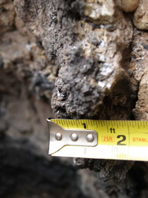
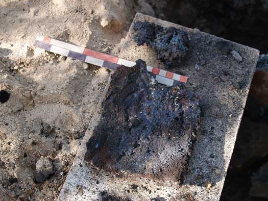
The inner surface of the smelter, at the rear (away from the tuyere) at base level. The inner surface of the bellows plate, with the position of the tuyere at the top. A close up of the clay liner, just at the top edge of the bellows plate.

The fracturing of the smelter liner can be easily seen in the left image. The dark band near the bottom of the wall marks the rough location of the slag bowl. This zone is protected from oxygen in the air blast from the slag. There is virtually no change to the appearance of the earth base seen at the bottom of the image. A layer of wood ash from the pre-heat phase keeps significant temperatures from penetrating downwards. There is little or no slag remaining attached to this rear wall, directly opposite (furthest away from) the tuyere.
The remains of the bellows plate (center image) are less revealing. The thin plate had withstood the high temperatures extremely well, up to the point when it became necessary to switch to the insert style tuyere. When this was done, the largely cracked clay that had been holding it in place broke away, the end result was that the plate shifted inwards into the furnace itself. To seal the new air system, several handfuls of clay were slapped on the outer surface (clear in the image of the modified air system above). In the end the ability of the thin plate to radiate heat off its outer surface had been eliminated, so melting of the plate was to be expected.
The last image above shows the effect of the high furnace temperatures on the structure of the clay cobb walls. The fragment seen to the right above was the edge of the wall where the initial cut had been made to insert the bellows plate (upper right as you look at the front of the furnace.) The remains of small amounts of slag and partially sintered ore particles can be seen adhering to the inner surface (inside of furnace on left side). The discolouration from the clay sintering to ceramic as the heat penetrated is also easy to distinguish. It is hard to tell if the wall has sintered entirely through all the way to the outer surface. Rubbing the outer surface with water did not remove any material as a slurry, which suggests the wall at that point at least, had been fired right through. The ceramic remains extremely porous because of the mixture of straw, and could not be expected to survive any more than a couple of winter freeze / thaw cycles.

Conclusions:

1) Overall set up
It was clear that working from the top platform did not pose any significant problems during the main smelt sequence. Our standard has been both charcoal bucket and ore scoop on long handles. this done to keep hands out of the hot exhaust gasses at the top of the smelter. It would have been easy enough to stand on the ground beside a built up sod in frame structure and make the charges. This is thought more likely than working from the top of the platform, as to do this would make it difficult to fill the buckets of charcoal (specifically) from the large pile of fuel required for a smelt. Without a handle on the bucket, it would be necessary to have another worker pass up each bucket, or the one adding charges to constantly hop on and off the structure.
A clear increase in difficulty was noted when it came to attempting make a top extraction of the bloom while working on top of the platform. Normally the body of the smelter protects the lower half of the worker, who is reaching down to a level roughly at the ankle. On top of the platform, now the reach to the slag bowl is extended a further 60 cm lower, while the entire body is exposed to the heat of the furnace. What eventually happened is our team was working while kneeling so they could reach the bottom of the furnace. This clearly did not allow for the same amount of force or leverage to be available.
2) Use a medium walled clay cobb -
There was no significant problems encountered with the change from a 8 cm to a 5 cm wall thickness built of straw and clay cobb. The smelter liner was found to be more fragile with the thinner walls. The use of the bellows plate largely reduced erosion of the walls, so no significant reduction of thickness from the high temperatures was observed. With more care taken to reduce damage on extraction, it is expected that the 5 cm walls would have withstood at least one more firing.
More experimentation should be undertaken here. It is expected that the 3 cm wall thickness will experience significant cracking and prove too fragile to survive the extraction process without significant repairs. Replacing the chopped straw with dry horse manure is also suggested for the 3 cm thickness.
3)) Location of the hand bellows -
The primary problem here was the size and position of the frame supporting the bellows within the working slot. Although it was relatively easy to see the bellows plate and blow hole, the direct access to this area was limited to standing along the edge of the frame. This made it more difficult to attempt any manipulation of the developing slag bowl through the blow hole. (This was part of the reason for the blockage encountered.)
The tap arch itself proved totally impossible to access. It might have been possible to lay down under the bellows frame, with a bellows operator straddling that worker while pumping continued. This was just not considered practical. With no access to the tap arch, easy control of the slag volumes was just not possible.
For both these reasons, it is suggested that it would be more likely that the bellows would be hung from extensions off the timber structure of the smelter than supported on a separate frame. Another possibility is that the bellows on its frame would be moved some distance back (and to the side?) of the smelter structure, and some type of air pipe be used to channel air to the tuyere / air nossel. This could easily be fabricated from a tube of heavy leather or a hollowed out length of wooden branch.
In any case, a bellows located inside the working slot would certainly have to be removed if a bottom (front) extraction method was to be undertaken. Our normal practice has been to continue with gentle air during extraction, this to keep the slag from solidifying around the bloom. This would be impossible with a frame mounted bellows located in the working slot. Extremely fast work would be required to pry the hot bloom out of the hardening slag. It is most likely that the end result would be more damage to the lower front wall of the smelter itself. The continuing air blast also makes it possible to recharge the smelter to use it as a giant forge for re-heating the bloom after the initial compaction. This allows for multiple working sessions for consolidation and cutting. A frame mounted bellows would have to be constantly moved in and out of the work space to allow for this.
A) Use a bellows plate construction
B) Use blow tube arrangement for the tuyere
It was clear that the team needs more experience working with this type of furnace set up. In itself, the bellows plate was found to work extremely well. The thinner material did in fact withstand the higher temperatures surrounding the air blast quite effectively. Leakage around the plate was due to clay shrinkage, as the body of the smelter had been baked dry before the plate was installed. Fitting the plate while the body of the smelter is still damp is expected to greatly reduce (if not totally eliminate) this effect.
The blow hole arrangement proved to be more of a problem. It was clear that the system was working correctly for the first portion of the smelt sequence. Consumption rates were slightly reduced from those seen with the insert tuyere, but still in within what was considered the effective range. (A rate of between 6 - 12 minutes per 2 kg charcoal is sought, for this experiment the rate averaged 13 minutes per charge.)
Problems were encountered as the slag bowl began to reach the level of the air hole, Attempts to clear the hole were compounded by the restricted access because of the bellows frame combined with the lack of experience on the part of the operators with this type of air system. Modification of the air tube and adapting the air hole to correctly fit should be made (in line with suggestions by Michael Nissen)

The production aim for this experiment was for a 3 - 5 kg bloom, similar to those suggested for Hals (size in range of 15 x 15 x 10 cm). Despite the near disaster of the blocked air hole, the team was able to apply past experience to salvage the smelt, producing a 4.9 kg bloom.


Text and photography © 2008, Darrell Markewitz