Vinland 4 - June 12, 2010
Working towards a reconstruction of the L'Anse aux Meadows Smelt
Smelt Report
This smelt was primarily a test of presentation method of the Vinland smelt,
part of the general dress rehearsal in preparation for DARC's demonstration
event at L'Anse aux Meadows NHSC, August 15 - 25, 2010. Primarily intended as
a demonstration, it was undertaken using only Viking Age tools, and in Norse
clothing. The construction of the smelter and the layout of the working space
was the same as that indicated by the archaeology of L'Anse aux Meadows. (Details
of the logic behind this series)
The working team was :
Darrell Markewitz - construction / smelt master
Ken Cook - lead hand
Sam Falezone & Pierre La Fountaine - bellows
Images are by David Cox
One of the primary concerns with working against the LAM evidence is that the
furnace construction is a simple clay and sand mix. Our own past experience
with this material has almost always resulted in heavy cracking to the furnace
walls. (Although it should be noted that others, especially Sauder & Williams
do NOT have that problem!) This was certainly the case in this experiment.
This smelt was also predicted to have lower yields than our usual.
First, the ore analog mix used thought to be part of the reason. The analog
used here was a blend of Spanish Red oxide and Hematite grit.
The main reason that low yields are predicted for these smelts is the method
of air delivery - use of the human powered Norse double bag bellows. The air
volume available is based on a theoretical delivery, the there has proved to
be large variation in delivery between individual operators.
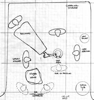
Theoretical Layout
The physical layout of the equipment is based not only on the archaeology, but
also how that evidence has been interpreted by the working smelt team based
on its past experience.
With the remains of the smelter base placed slightly to one side of centre,
the bellows has been positioned to the wider side (the left as seen here). Use
of a leather Y coupling allows for just enough room to permit clearing of the
tuyere as required. The evidence suggests a tap arch towards the open front
of the structure. The large pit to the front left is interpreted here as the
stable mounting of a wooden stub to hold a large stone anvil for the consolidation
step. Through some luck, a large stone with relatively flat surfaces had been
found that was fairly close to that found at LAM to serve as this anvil. The
pile of charcoal was placed to the right rear, and ore addition to the right
centre. A slack tub placed to the right front corner cools working tools close
to hand.
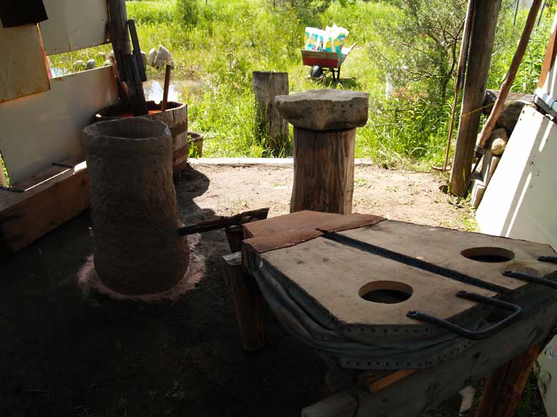
Bellows Operator view, from the rear left corner out the open front
of the working space. (Before drying fire in furnace.)
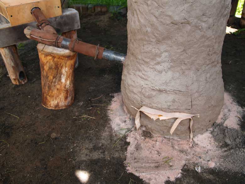
As with other furnaces in the Vinland series, the walls were built up of a simple
clay and beach sand mix, at roughly 50 / 50. The starting interior diameter
was 23 cm (9 inches), produced by using a metal form wrapped in newspaper. Wall
thickness initially was roughly 5 cm. The furnace was constructed on top of
a circle of fine white silica sand (to help distinguish this experiment from
earlier ones). As each course of clay was built up, the form would be removed,
and the interior filled with a dry mix of wood ash and beach sand (also a 50
/ 50 mix). This helped to stabilize the structure, speed drying of the clay,
and allow the form to be raised for the next clay course.
First course completed
with packing added - note the shape is cylindrical at this point.
As the construction continued, it became apparent that the first batch of clay
had been mixed up a bit too wet. Despite considerable care to prevent downwards
force as the next two upper courses were applied, the base level started to
slump under the weight. The end result of this was not only a thickening of
the lower wall, but also a considerable belling outwards. The end result was
a pronounced 'pot belly' shape instead of the normal cylindrical or tapered
shaft. This increased the diameter of the smelter to closer to 28 cm (11 inches)
at tuyere level.
As ideal air volume is related to cross section area at that point, it was expected
that there might not be enough air produced by the Norse bellows. Such lowering
of available air was expected to also lower potential bloom yield. At the intended
diameter of 20 - 22 cm the ideal air volume would be 500 + litres per minute.
Expanded to 28 cm the ideal air increases to closer to 1000 + litres per minute.
(This is well beyond the ability of the test
bellows to produce.)
Although the initial build was to roughly 65 cm, the slumping reduced this height
to closer to 60 cm. The next day an extra layer was added to the top of the
walls to extend these to roughly 68 cm (26 1/2 inches).
Measurements of the completed
furnace.
Cut out Tap Arch, showing increase in wall thickness at base to about 10 cm
- due to slumping.
Furnace with tuyere set in place, showing final shape after slumping of the
walls (just before pre-heat)
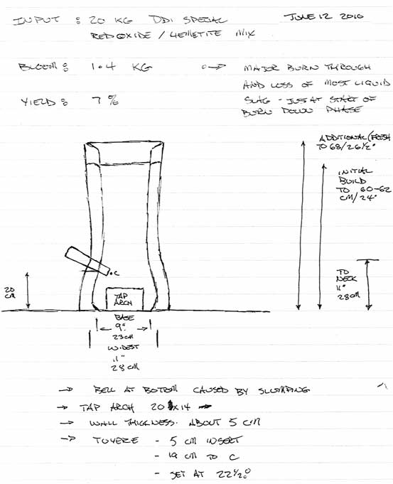
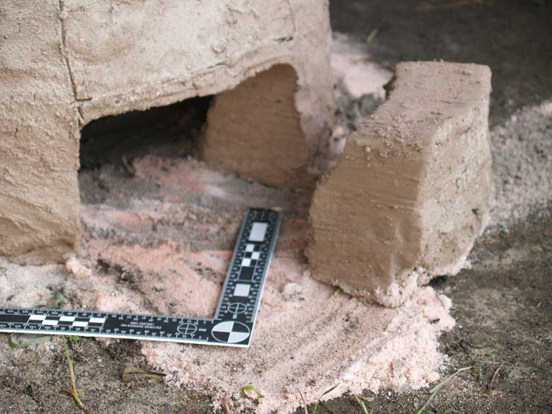
A small tap arch was cut into the base, 20 cm wide by 14 cm tall. This was separated
from the parent wall with a thin layer of birch bark to keep it from re-sealing.
The tuyere was forged from mild steel pipe (standard schedule 40). A taper was
created over roughly the last 10 cm, reducing the starting interior diameter
from 3.5 cm down to 2 cm at the tip. A series of three sewn leather tubes, held
tightly in place with thongs, jointed the tuyere to the bellows tube. The effect
of these leather couplings was two fold. First their flexibility reduced any
vibration or movement from the working of the bellows from being transmitted
to the tuyere mounted in the fragile smelter wall. The second effect was to
prevent heat absorbed by the metal pipe from being radiated back up the system.
In the centre of the couplings was a leather Y tube, the last branch filled
with a tapered wooden plug. Removing this plug allowed to probe down through
the tuyere to clear any blockages as might be required. Overall this system
proves quite stable and effective.
The tuyere itself was set up as has been proven to be the ideal through past
experiments. It angled downwards at 22 1/2 degrees, protruding into the smelter
5 cm proud of the inner wall. The centre of the tip was positioned 19 cm above
the ground level base of the furnace.
View of the interior after the initial
drying fire. Note large crack extending down to the right of the tuyere.
This was the crack that would cause problems later in the smelt
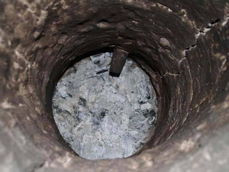
The night before the smelt, the normal small drying fire of wood splints was
started inside the furnace. Four to six pieces of hardwood, split down to roughly
thumb diameter, were added at a time. The drying process was conducted with
primarily natural draft caused by slightly pulling back the tap arch block.
The bellows was only used when the fire was in danger of completely going out.
The process heated through to the exterior, making it 'almost too warm to hold
your hand to'. After about three hours, a metal cap was placed over the top
of the furnace, and the coals inside were allowed to burn down to ash (as seen
in the image above, taken the next morning).
It was discovered there were several large cracks which ran from the top of
the furnace right down to the base. The largest of these was opened up to about
1 cm at the top. As the initial pre-heat fire of wood splints was started, an
attempt was made to use what little softened clay remaining on hand to wedge
shut these cracks. As the damp clay was sure to shrink and crack itself, it
was only expected to reduce, but not eliminate, the effects the large cracks
would have on the progress of the smelt.
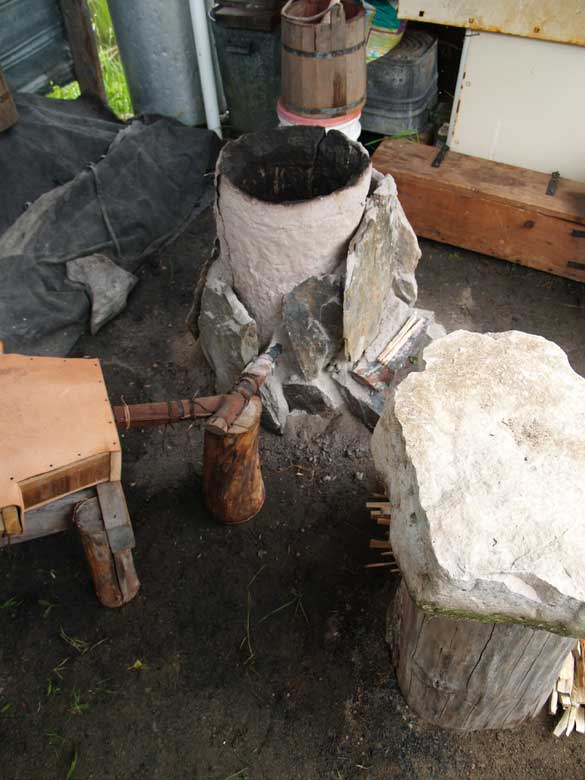
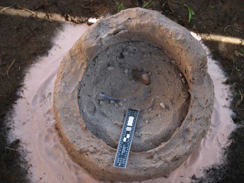
At the start of the pre-heat, stone
slabs packed with ash and sand mix.
As with other furnaces in the Vinland series, the clay inner liner was surrounded
by a series of flat stone slabs. The clay core of the furnace would certainly
have endured a single firing event without any additional support. The primarily
function of the slaps is actually to hold a layer of packing material in place,
the same 50/50 mix of wood ash and sand used during construction. On exposure
to the high temperatures of the smelter, this mix actually will form a simple
glass, which also will help to plug cracks. If the holes become over large,
the packing will run into the inside of the smelter, which can result in excessive
slag formation. This itself can cause problems with managing the smelt.
As the first load of rough charcoal was added, there was considerable problems
with explosive spalling, especially at the outer top areas of the clay walls.
New cracks developed, existing ones widened.
The conduct of the smelt was based entirely on past experience, the look and
sound of the working smelter, rather than objective measurements of time and
temperature. All the workers had past bellows experience, both at the smelter
and as working blacksmiths. This allowed there to be a relatively constant supply
of air over the entire progress of the smelt. This despite switching operators
every 10 minutes or so, and individual fatigue over the roughly four hours of
the smelt. Consistency of air delivery was based mainly on sound, as individual
operators had differing styles of stroke. Delivery produced is a combination
of length of the stroke, frequency of the stroke, plus amount of force used
for the stroke. For most operators, one stroke is required each second, roughly
the rhythm of a healthy heart's beat.
A wooden scoop had been made of green birch wood, of a size to hold about a
'double handful' of ore. Earlier measurements of the Dark Dirt analog showed
that the average weight of a slightly rounded scoop full was 540 gms.
The total amount of ore had been pre-measured to 20 kg of the Dark Dirt 1A analog.
In fact this amount 'filled to heaping' the wooden bucket set aside to hold
the ore. This material contained a combination of Spanish Red oxide and granular
Hematite. The available Fe content was calculated
to be 55%
Charcoal was added by 'a standard bucket'. A wooden bucket had been marked to
contain the same volume as our standard (modern) bucket, which contains about
1700 gms of sized, dry charcoal.
Besides attempting to maintain a constant air flow, the only other control was
the distribution of ore additions related to charcoal consumed. Again the pattern
used was based on experience gained from past smelts. The entire interior of
the smelter to come up to full temperature, when the glowing orange of ignited
charcoal climbs to a level about 40 - 45 cm above the tuyere (about 7 cm below
the top). At this point ore is added, distributed evenly through each bucket
load of charcoal. The first four additions of ore consisted of single scoop
measures per bucket of charcoal. The next three charcoal measures included 2
scoops. The next two additions included 3 scoops. The last bucket included the
remaining ore, just over 3 scoops.
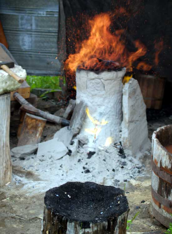
Late in the smelt. Gases escaping from the
widening cracks are evident.
The stone slabs have been re-positioned several times in an attempt to plug
the worst of the gaps.
Image by David Cox
It only proved necessary to tap liquid slag once during the main sequence. This
was roughly 2/3 the way through the process. The tapping was done through the
front arch, moving the block away and punching a small hole through the slag
bowl on the side away from the tuyere. Generally the tuyere worked cleanly,
clearing slag obstructions was only required a couple of times. The impression
was that the higher pressure pulses of air produced by the direct stoke with
the Norse double bag bellows was assisting to keep the tuyere clear.
It had been expected with the various cracks that developed that the furnace
would self tap. This proved not to be the case through the bulk of the smelt.
A dramatic event near the end of the main sequence was to alter the course of
the smelt.
The last charge of ore, about 3 1/2 scoops, had been added. One last full bucket
of charcoal had been added to cover this, and the burn down had begun. The top
level of charcoal had dropped down about 10 cm. At this point the last ore addition
would have fallen to roughly just above tuyere level. Suddenly, a massive pour
of slag vented out of the crack just to the side of the tuyere (towards the
rear, away from the tap arch). There was a bit of a mad scramble in an attempt
to halt this flow. (I was working the public rope line outside the smelter when
this happened). In the end approximately a litre or more of liquid slag was
lost.
The first, and likely most important result was a considerable drop in internal
temperature within the smelter. As soon as the iron rich slag had cooled enough
to allow it to be picked up, pieces were returned back into the smelter, along
with about another half bucket of charcoal. The hope was that this material
would melt, and some of the iron it contained would be deposited to the developing
bloom. This certainly proved not the case, as the furnace had lost enough heat
that those pieces never did melt.
The regular burn down continued, to a point there was perhaps 10 - 15 cm of
charcoal remaining above the tuyere / slag bowl level. The normal top extraction
method was used : reducing air flow, scooping out the remaining charcoal to
uncover the top of the slag bath, hammering the top of the bloom in place with
the wooden log 'thumper'. The bloom with its usual loose coating of 'mother'
was pulled free easily with the bloom hook, then grabbed with the bloom tongs
and moved to the stone anvil.
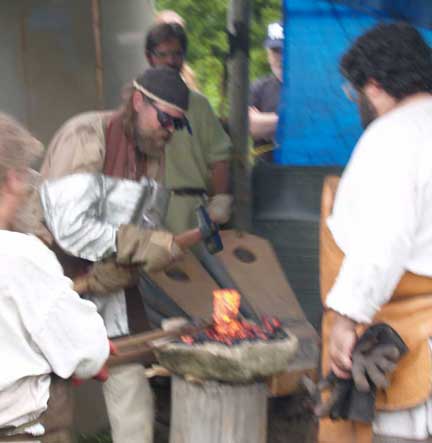
Working the bloom, near the end of the consolidation step.
Note the pile of loose 'mother' scattered on the stone anvil.
Image by David Cox
As the bloom was pulled from the smelter, it was immediately obvious that the
mass was significantly less that what has been come to be expected from earlier
smelts. Our normal practice is to lay the bloom directly on the top of a wooden
stub, rather than employing any kind of anvil. Lack of experience working on
a stone anvil caused the incorrect assumption to be made of the blooms character.
The dull 'whack' sound on each hammer stroke was so like the sound of hitting
cast iron, this was pronounced to be the quality. In retrospect, the mass was
also considerably colder than is normal, even as it was pulled from the furnace.
In the past the newly extracted bloom is closer to a 'bright yellow' welding
heat. In this case the metal was a best a 'bright orange'. As it was hammered,
it was just not hot enough to be welded up, but instead was more mechanically
compressed. The result was a brick shape, containing a lot of cracks.
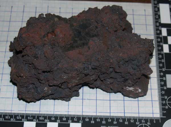
Partially
compressed bloom, what was likely the upper face when inside the furnace.
The mark from the grinding test can be seen.
The total size was 12 x 6 x 4.5 cm, weight at 1400 gm, with a second small irregular
piece at about 150 gm. With a total starting weight of ore at 20 kg, that equals
a yield of only 8%. Far less than expected! A later spark test on the centre
face of the brick suggests a nice low carbon iron.
Some valuable comments:
Kevin Smith reminded me (again) of one of the truisms of archaeology
: that 'absence of evidence is not evidence of absence'.
" The preserved thickness of fragments of the walls of a smelting furnace
may only be telling you how far intense heat penetrated into the unfired clay
of the original walls and fired it into a more durable ceramic. In other words,
the "as built" walls may have been far thicker but the outer surfaces,
being less intensely fired or still semi-raw, may well have eroded completely
and washed away into the soil matrix at the site. ...
" In other words, without seeing the original, actual samples from
L'Anse aux Meadows, I would not put much trust in reconstructing a tapered wall
thickness from 10 cm (base) to 5 cm (top)...unless the actual original pieces
from L'Anse aux Meadows are so well preserved that it's clear that all of them
have well-preserved exterior and interior surfaces. If they do not, then what
the L'Anse aux Meadows published furnace wall fragments are actually telling
you is ONLY that the furnace walls were *at least 10 cm thick*. I do not think
you can assume that they were any thinner unless they do have furnace wall fragments
just 5 cm thick with well-preserved and distinct finished surfaces on both sides.
"
Lee Sauder (and others) have clarified the value of sand in
the construction of walls:
" You need to make sure you're using a good clay, it needs to be heavily
grogged with sand or clay grog, it needs to be mixed properly (not too much
water), it needs to be worked and kneaded (wedged), and it should rest before
you use it.
...
" The organic fibers are nice, but if you can't use them, just increase
the sand or grog so that your clay content stays low. The sand doesn't change
size much when it gets hot, the clay does. "
Conclusions:
In retrospect, the use of unknown clay, a choice caused by simple time pressures
and supply problems, appears to be the main cause of the construction problems
with this furnace itself. This statement based on the fact that this there were
three other furnaces constructed earlier on the same layout, and the methods
employed were those fairly standard for the building of many others. With the
new clay the only major variable, this certainly appears to be the source. My
plan for the actual LAM demonstration smelt is to have enough of of standard
clay on hand for the build. There remains the possibility of acquiring enough
of the local clay to build the furnace of. This however would then add a second
level to the experiment itself.
Some better understanding needs to be acquired on the effects of various mixtures
of sand and clay. I had originally thought that mixing 50 % sand was a generous
amount, but the advice given based on the direct experiences of others suggests
this is not the case. Without definite knowledge of the exact mixtures utilized
at LAM originally, this all remains guess work at best. The furnace used for
Vinland 4 did experience hardly any interior wall erosion, normally a significant
concern on at least the first firing of such small clay wall furnaces. A number
of others have explained that increasing sand or adding grog normally helps
*prevent* cracking. Generally this was linked to problems during the actual
firing cycle of the furnace, which was not the case here. Since the cracking
developed during the initial drying, some modification of that method should
be considered.
The exact composition of the ore used was not recorded. It was however a mixture
of our DD1 (red) plus some amount of granular hematite. The straight DD1 (at
45% Fe) has proven to produce lower yields (in the range of 15%) in the past,
so perhaps the low yield on this experiment should have not been so unexpected.
The addition of any amount of hematite (at 68% Fe) could have only served to
enrich this ore.
There has been some indication that it may be possible to utilize locally gathered
primary bog ore for the LAM demonstration smelt. My plan is to bring enough
of the previously tested DD2 (black) analog. Switching to an unknown and untested
ore is most likely to modify the entire theme of the LAM smelt from 'practical
demonstration' into 'experimental archaeology'. Consultation with Parks Canada
would certainly be called for before switching the focus.
The other large variable most likely to impact bloom formation is the air system.
As has been indicated, the working volume of the Norse type smelting bellows
may not have been adequate to produce enough air, considering the expansion
of the slumping furnace from the planned 22 cm to 28 cm internal diameter. Low
air almost always equals low yields and less dense blooms, both of which occurred
in this experiment. The other use of the same human powered system (Vinland
3) also resulted in lower yields than expected, despite the use of a significantly
higher iron content ore. It is hoped that with more practice (and a solid working
team) fluctuations in delivery (thus temperatures) can be leveled out.
Text and photography © 2010,
Darrell Markewitz
Images by David Cox are indicated