Slag Pit Furnace
'Celtic Iron Age'
October 9, - 2011


Short Shaft Furnace using Bratton's Run rock ore

Team Members: Darrell Markewitz, Marcus Burnham, Neil Peterson,

The reason to run this system was a preliminary test towards a possible public demonstration at the 'Earth Air Celtic Festival', Goderich, for early August 2012.

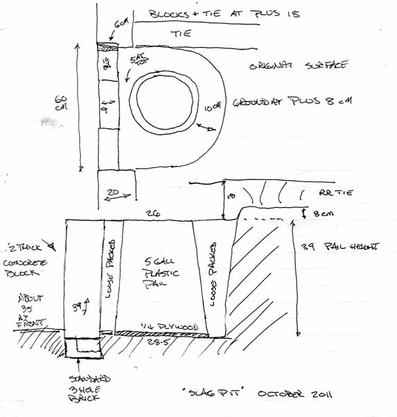
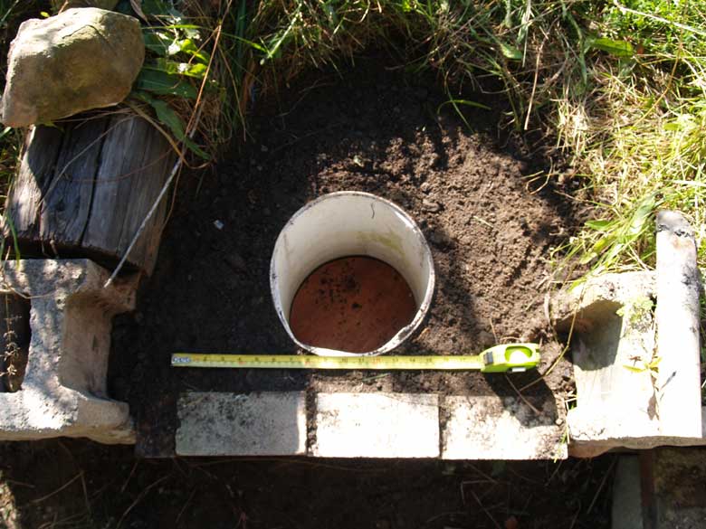
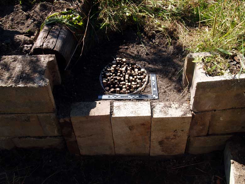
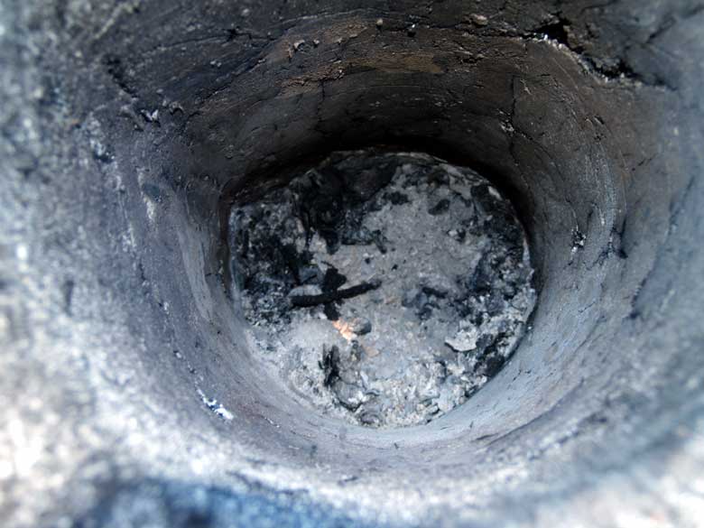
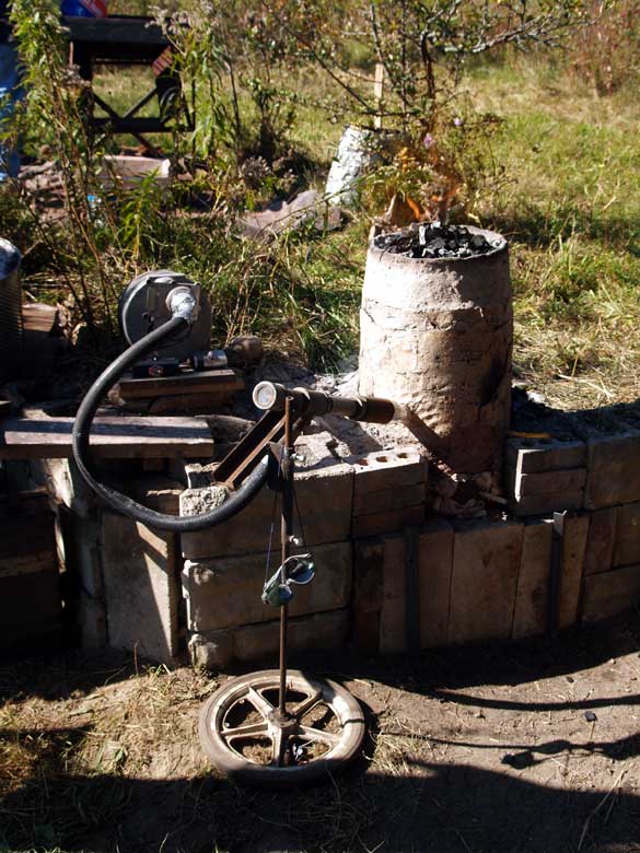
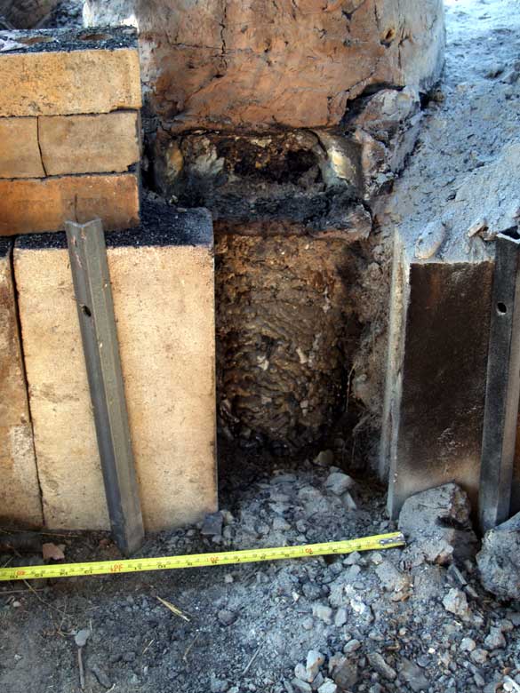
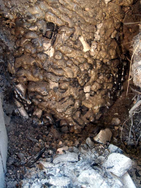
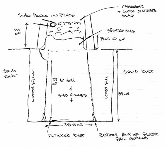
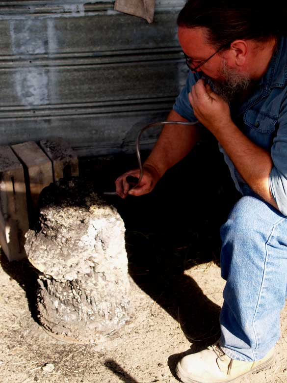
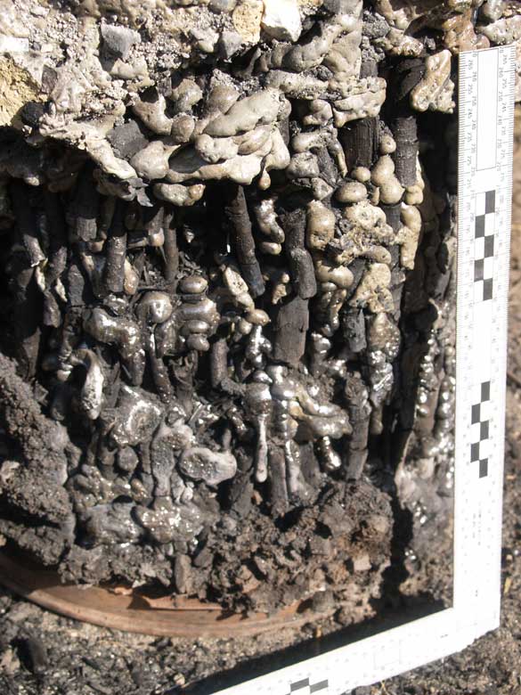
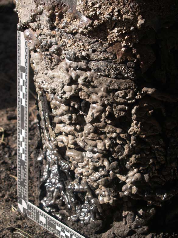
The Slag Pit style furnace is an older type than the Slag Tapping furnaces that have dominated our work to date. The base of the furnace has a shallow hole or pit dug below ground, which is then filled with some kind of vegetation. In use, the vegetation at first supports the burning fuels in the furnace itself. The inital slag forms into the normal bowl shape below tuyere level. As both heat increases and slag accumulates, at first runnels of slag will drip down through the vegetation. Increasing heat first carbonizes the plant materials, then the weight of of the slag mass slowly settles into the pit. Designed and managed correctly, there is no need for additional tapping of slag. The upper furnace structure itself varies, ranging from smaller bellows blown to larger natural draw types.

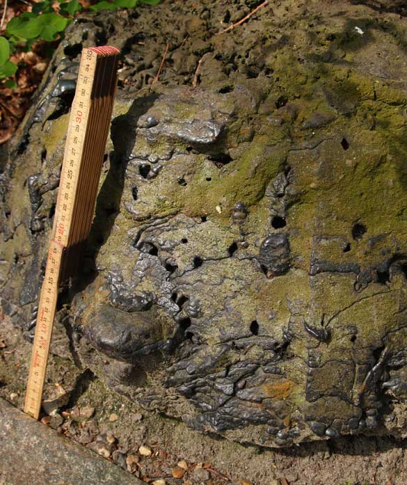
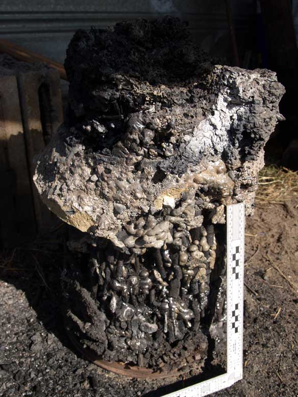
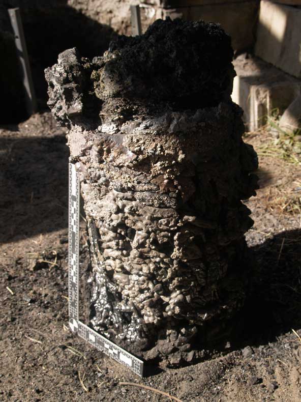
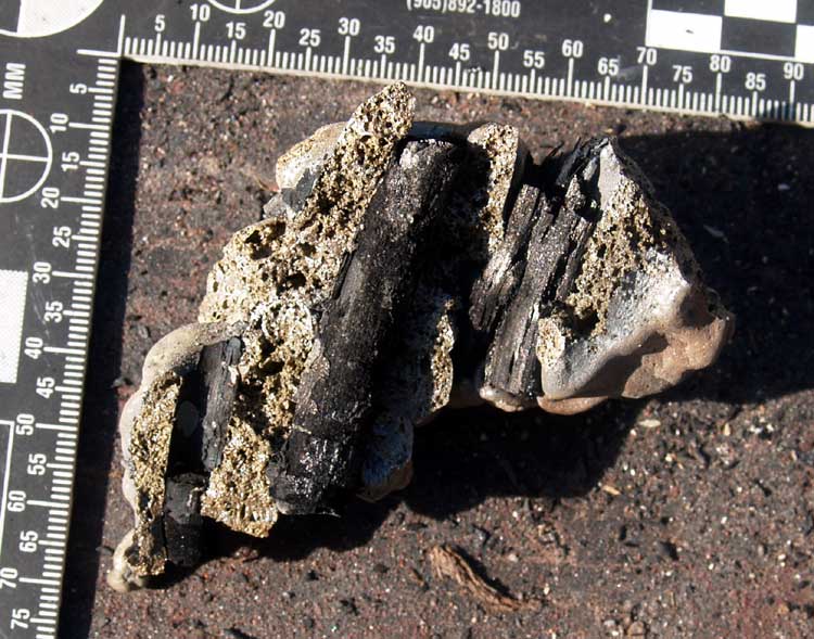
The slag pit arrangement was common throughout Europe, roughly up to the end of the Roman period. The slag blocks created are almost industructable, and thousands remain. In Denmark alone, over 2000 have been found. Typically these are roughly the size of a bushel basket. (Image at the right is from the lower Jutland area, from my 2008 trip.)

I had seen both Jake Keen and Jan Jennisen both build and fire slag pit furnaces at the 2008 Heltborg 'Iron Smelting Seminar at Thy'.

Those interested in more details on the slag pit furnace are refered to the work of Thijs van de Manakker :

A short photo essay

'Experiments with a Slag Tapping and a Slag Pit Furnace' (PDF download)
Originally published in 'EARLY IRON PRODUCTION Archaeology, Technology and Experiments' - Edited by Lars Chr. Norbach

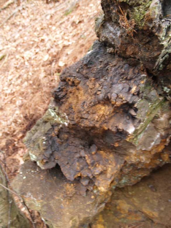
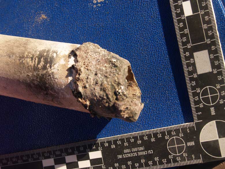
The ore used was an *untested* rock ore I had gathered at the Bratton's run site in the area of Lexington Virginia during Smeltfest 2011. This is another abandoned Colonial / American Civil War era mine works discovered by Lee Sauder & Skip Williams :


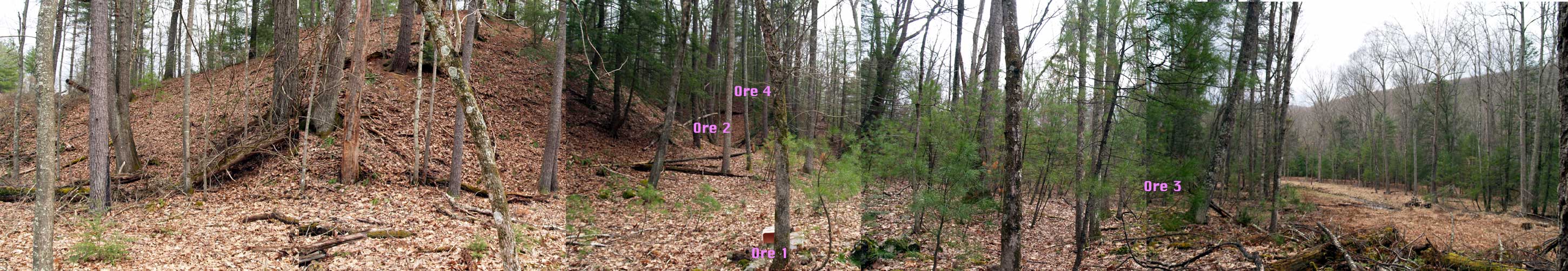
Pannoramic View of the Bratton's Run Site

With minimal experience gathering rock ores, I had pulled from four different locations within the original cutting. The material used for this smelt was what * I * had thought was some of the better of the materials collected. This was from a vein of ore that ran through the centre of the original cutting, the specific location was from the upper right area of the cut (Ore 4 on the panoramic view of the site.)

Furnace Layout

Layout of the Pit

Pit Depth
39 cm
Pit Diameter
26 top - taper to 28.5 base
Furnace Internal Diameter
25 cm
Stack Height (above tuyere)
43 cm
Tuyere Size
standard 2.5 cm dia ceramic tube
Tuyere Angle
22 degrees down
Tuyere Penetration
5 cm
Tuyere Height
13 cm
above ash base

Layout of the Furnace

The Construction Phase

The initial work consisted of clearing away the remains of a previously used smelter from the working location. This furnace had been constructed and fired in June of 2008, and was in surprisingly good condition up to spring of 2011. At some point over the summer the metal drum protecting it from rain had been knocked over (some animal?) which had broken up part of the top section.

Outter surface, showing the sintered ceramic core remaining, while most of the surface clay and straw cobb had washed away.

Internal view, with the tuyere at the right side. Note that there was very little errosion or internal damage.

A standard 5 gallon plastic pail with the bottom cut off used as a form (placed upside down). A set of concrete half blocks were used to contain the loose dirt fill.

The pail was packed with pieces of brush (mainly willow) with diameters ranging from .5 to 1 cm. These had been carefully cut to make a relatively flat surface at the top.

Our standard sheet metal forms were placed above the pit to establish the interior and exterior diameters. This produces a furnace with roughly 7.5 cm thick walls.
The mixed clay / straw / sand mixture has been built up between and to the top of the forms. The top edge has been angled inwards to assist in charcoal loading later.
A view into the interior, just after the metal forms have been removed.
The ceramic tube tuyere, re used from our last smelt. There is some reduction of the cyclinder to a slight cone. More significant, the tip has been erroded to a vertical angle related to the initial 22 degree down angle position.
The initial drying fire, later on build day. A 3cm thick pad of wet straw was placed over the branch ends, this in turn covered with 5 cm of charcoal fines.
A small tap arch was cut into the side of the base, but was never utilized in the smelt.
Base of the furnace the next morning, showing some heavy cracking. This was primarily due to tearing of the inner paper liner during construction. The collapsed newspaper had prevented individual clay applications from blending together.
A view inside the furnace to the natural ash and charcoal layer from the drying fire (next morning). The tip of the tuyere can be seen to the left. A large crack extends along the top of the image.
The straw had carbonized, but still remained in place.

Main Smelt Sequence

Images in green by Neil Peterson

During the warming fire, measurements of the air delivery of the Smelting bellows were made. See the separate section detailing the results. The full air system in place.
Charcoal fills the furnace, waiting for the full ignition of the reaction column.
About two hours into the smelt, white smoke is seen escaping from between the base blocks. This is thought to be from burning plastic caused from the heat of dripping slag into the pit area.
The furnace had been equipped with holes at 10 cm intervals, allowing for internal temperature measurements. These were taken roughly every hour, using a digtal pyrometer. See Furnace Temperatures
After burning down, reducing air volume and scopping out remaining charoal to expose the top of the slag bowl. Available light shot illustrates the temperature!
Same view, only illuminated by a flash, tuyere point to the lower left.
The ragged surface of the slag bowl / block is clear. Note that there is very litte errosion to the inner clay surface of the furnace.
'Where is the iron?' Pondering the problem after what had seemed a smooth smelt sequence (and almost 50 kg of ore added!)
Pulling away the front supports to expose the slag block in an attempt to find some iron.
After a long day, we have 'beautiful slag'... and decide to leave the furnace to cool and explore more systematically the next morning.

Excavation
Cool slag block in place below the furnace - completely filling the pit.
Top of the slag block in place, after the furnace itself had been lifted clear of the pit. The lower 10 cm or so of the furnace had broken clear, and can bee seen to the right hand side.
Close up of the front side surface of the slag block. The pail had allowed individual runnels of slag to cool before buring away, resulting in a shiny glass surface. Note the pale green colour, and indication of virtually no iron content here.
Digging away at the loose dirt fill material to free the slag block.
This overall shot shows the relatively intact furnace, lifted in one piece and set to the rear.
Slag block entirely cleared free. The tuyere point was to the upper left corner. Note the difference between the slag bowl material and the lower dripping slag.
Drawing of the slag block as it was formed.
Bottom of the pit after the slag block was pulled free.
Neil cleaning away loose ash and fine charcoal with a blowing tube.
Rear section of the slag block. The tuyere was positioned above the vertical arm of the scale. Close up of rear. Note the darker colour to the slag to the extreme left (away from the tuyere). This indicates some iron present in the slag at least. Individual pieces of branch, baked to charcoal, are clearly seen.
The lower rim of the plastic pail still remains, discoloured but not melted.
Front section of the block. Again the arm of the scale indicates the position of the tuyere. Mostly pale slag (no iron) here.
Close up of the front section. A detail of a slag block fragment. The frothy green, iron poor slag is wrapped around the branch segments, now converted to charcoal.  

Final Results
TOTALS
Time Construction about 5 + hours
Preheat 2 hours
  Main Smelt Sequence 5:45 hours
  Total Elapsed Time about 8 hours
Fuels Total Charcoal about 65 kg
Ore Total Added 48 kg
Slag Block Weight 40 kg
No Iron Produced

Smelt Data Sheet

It was clear that the failure here was with the selected ore body. This was considered questionable even from the start. A small amount of the DD1 analog, total about 6 kg, was addes about half way through the sequence. This may account for the runnels of dark slag (indicating iron present) seen at the rear of the block. Although it was hoped that this better quality ore might form its own small iron mass, it appears that this was not enough to overcome the generally low content of the bulk of the ore added.

It has been decided to retain the slag block as a reference sample. The area below the tuyere (where a bloom normally forms) is slightly magnetic. It may prove that a small amount of iron was produced, and remains trapped in the upper portion of the block.

Proof of concept was certainly delivered. The individual design of the furnace and the individual elements of construction did in fact operate as hoped. At one point the bowl was punctured by driving a rod down from the top, but other than this there was no significant problem with liquid slag blocking the tuyere. It should be noted that 'ore input against slag output' is very close to balanced, within the limits of a field experiment.

The furnace itself has minimal damage, and can be quickly repaired and re-set for another smelting event.

It is fullly expected that with the use of a propperly rich ore, the combination of slag pit with short shaft should function correctly. Other experimenters have advised that high air / consumption rates with their similar furnaces lead to cast iron production. Further tests would be required to make any valuable insights.


Unless Noted : Text and photography © 2011, Darrell Markewitz