Into Phase Three - Continuing
Experiments with Iron Smelting, based on Hals, Iceland
Note : For clarity, a number of terms are supplied with
definitions as are used in this commentary. Readers with knowledge
of iron smelting are most likely to be familiar with these terms,
and are asked to have patience for background explanations.
Introduction:
The team from the Dark Ages Re-Creation Company,
under the leadership of Darrell Markewitz, has been involved
in an exploration of Viking Age, Icelandic, bloomery iron smelting
methods, now for over a decade. This has been specifically centred
on the archaeology of a long duration, ‘industrial’ level production
site, located at Hals (west central Iceland). The original
excavations there were undertaken by Kevin P. Smith,
documented in his paper : ‘Ore, Fire, Hammer, Sickle : Iron
Production in Viking Age and Early Medieval Iceland.’ (1) As
well Kevin has become a good friend and advisor to our team over the
last twenty plus years, and has provided many additional details in
private e-mails and discussions. One important consideration that
must be made is that the excavations at Hals by Smith were only
partial, for example only a small portion of the area most likely to
contain the remains of additional furnaces was possible to expose.
The 2005 report only describes excavation down to the top part of
the individual furnaces, work was halted with the (unfulfilled)
expectation of returning later to resume and complete.
This experimental series started in 2007, with an initial concept
overview prepared : ‘Working towards an Icelandic Viking Age
Smelt - Based on the remains at Hals’ (2)
Our earlier iron smelting tests in this series
can loosely be broken down into two phases :
- Phase One / four experiments / 2007 and 2008 / testing individual
design elements
- Phase Two / four experiments / 2012 to 2016 / testing use of turf
builds, then combining elements from phase 1
In phase one and two, we were attempting to take the system that
Smith had proposed in his early paper - and physically test how
various elements would work individually and in concert into a
functional whole – of that proposed furnace layout. (3)
Looking backwards, it is obvious that much had
been learned about iron smelting in general in the gap between phase
one and two. I did not feel (even at the time) that I really did not
have a solid understanding on smelting process until into late 2008
(so not until after the first two of the Icelandic series
experiments specifically). The team shifted to our 'Vinland' series
over 2009 - 2010, and I did a lot of international project work over
2014 and 2016 - all before the end of phase two in this series. When
the initial planning of experimental testing for phase 3 was started
in winter of 2021, we had intended to return to the earlier 'boxed
turf cone' design. Against this, in spring of 2021, considerable
effort had been expended in gathering both timber for framing and
earth for fill as would be needed in the construction.
Long term experimental partner Neil Peterson
and myself spent several hours on Friday June 11 (plus many
additional e-mails) plotting out exactly how to proceed into a next
group of experiments. We were assisted by Rey Cogswell, who
brings experience in archaeological survey methods and recently has
joined the iron smelting team. Towards designing the current build,
we considered again what the evidence from Hals can possibly
suggest, especially in light of what we know now (after an
additional decade of experience, with over 60 more smelt
experiments, since we started this series in 2007). (4)
It is important to stress that the commentary
below is based on our own observations and interpretations over
period leading up to a full build the week of June 12 through 17, in
preparation to the scheduled smelt experiment at Wareham on June 19.
It is well understood that working from a published report and
images is most certainly NOT the same as an individual’s direct
personal observations on the actual ground itself. (5) To this end
full apologies are made (in advance) to Kevin Smith, for any
misconceptions or outright errors in understanding that may be
expressed below!
Considering Hals (again)
At this date recovering additional detailed
information about Hals is considered 'difficult to impossible'. This
puts us back to just looking at considering what we actually know
from the original published description - and considering fresh what
those elements might really mean.
A revised version of the elevation and profile of Hals group of
furnaces. Modified from original by Kevin Smith.
Smith had recently provided both a coloured
photograph of the central part of the excavated area, plus several
new versions of what had been originally much smaller sized black
and white diagrams, now with a colour coded key. The version
above has been adjusted and printed on to graph paper, with a grid
showing of 10 cm.
It remains important to remember that the time imposed on the
original excavation process certainly limited progress, with
only the top surfaces of slag bowls for furnaces 4 through 7
being exposed. Further details thus remain unknown.
There appears to be two loose groupings of furnaces, four
with slag bowls cleared away, four with slag bowls still in
place , numbered from the earliest (bottom most as excavated) :
Ia / Ib / II / III
IV / V / VI / VII
This grouping is based on what we feel are different features
illustrated, most especially the closely positioned set of
remaining slag bowl (a) bases of 4 through 7.
It is not clear how the feature ‘silt enclosure’ relates back
to the individual furnace shafts (b), as the position of
individual shaft bases moves considerably over the series as
exposed.
If the stilt enclosure relates to base 1A (the first, based
on overlap of features) this places the centre of that shaft at
approximately 100 cm from the north edge (right) and 80 cm from
the east (bottom). The actual total size of this silt pad was
not exposed, so remains unknown. It should be noted that this
more or less central position to the edges of the silt layer is
not present with especially furnace 2, or also furnace 3.
From the profile (which relates most closely to only furnace
3), the northern most edge of the ‘enclosure’ appears to be only
about 2 cm thick. At the edge of the excavated area, closest to
the base of furnace 3, The total height of this layer is about
20 cm (at the excavated edge shown in the profile).
Extending the thickness of the silt layer however almost
creates a straight ground level line running north to south.
Against this observation are the two lower boundary lines
within the slit, defined by charcoal layers.
(Are those related to the surfaces used for the earlier
building of furnace 1 and 2 ?)
The bounding line of the slit at the north and east edges
form relatively straight lines. Smith suggests (1a) that some
framing existed to establish the edges. Just how tall that
framing might have been is not possible to estimate, especially
in light of how thin the silt layer is shown on the profile
illustration.
The bottom of furnace 3 rests on top of this silt layer.
The profile illustrated certainly appears to relate back most
closely to furnace 3 - although the diameter of the shaft shown
in the profile (plus 35 cm) is quite different than what is
shown in the elevation (about 28 cm).
The furnace wall in the profile shows nothing indicating
a liner.
What is seen are five layers of cut turf (c), measuring about
50 thick straight across, about 80 cm from inner most to outer
most edges at the base, now clearly slumped to the south
(towards the shaft).
The inner three lines of turf are raised up on the uppermost
layer of silt, which shows as about 10 cm thick, the outer two
layers resting on the layer below.
In the text description, furnaces 4 / 5 / 6 / 7 are described
as “… a stacked series of C-shaped, shallow bowls of slag, each
25 - 35 cm diameter and 5 - 10 cm thick, and each with a lower,
“broken-out” zone on the eastern side of the ring.” (1b)
Applied to the elevation diagram, this would suggest
the indicated dark brown shapes mark these slag bowls, with
the medium brown the bloom depressions (these colours not
identified in the diagram key).
There is a long ’tongue’ marked by charcoal running to the
east away from the cluster of furnace bases, this is more or
less centred on a line that runs between furnace 1 and 7.
To our eyes, these last two factors clearly indicate that at
least the last series of furnaces (number 4 to 7) employed
bottom, side, extractions of the blooms.
Both seen in the elevation diagram, and
described in the text, are the location of a number of stones,
placed around the extraction side of at least furnace 7. These
are described as “Flat, fire-shattered pieces of basalt, many
with adhering slag…” (1c)
Although this may seem obvious, to be ‘fire effected / slag
attached’ these stones must have been directly against the interior
of the furnace (so any clay liner built around the stones). A
functional build would be to frame an extraction arch with stones,
laid like a course of bricks, with one larger slab laid over the top
as a lintel to support any upper structure. This kind of framing
becomes even more important with the kind of turf enclosure seen
from the profile at Hals. The cut turf pieces have very little
structural strength of themselves, so any kind of gap around the
furnace inner surface requires a fire proof material for this
framing. In a working furnace the open part of this extraction arch
could have been filled by more stones, a clay plate, cut pieces of
turf, or some combination of these. How this might be done must be
considered an unknown, as this fill material would have to be pulled
clear while hot during extraction, so is most likely to have been
tossed off the working area for simple safety.
Another important element to effective furnace
operation is the dynamics of air supply. At Hals, there was nothing
recovered indicating directly the use of ceramic, copper alloy or
iron tuyere tubes. The only remains found suggestive of the air
supply system was a single clay fragment with “... a circular,
vitrified opening ...” (1d) which was later described as 'suggesting
a 5 – 6 cm diameter'.
This could mark the clay surrounding an insert style tuyere
tube (of unknown material) a hole that later in the smelt had
allowed hot gasses to escape around its margins.
Alternately the fragment could be the opening for some
variation of the ‘blow hole’ method (where the air supply tube
is placed just touching, even proud of, a hole cut into the
furnace wall).
This arrangement would not create any damage to
metal or ceramic tuyeres, and might even allow the use of bone,
possibly even wood tubes. With use of a blow hole, there has been
found to be a serious impact on air penetration into the furnace, in
turn changing the dynamics of how heat positions. This results in
higher, shallower slag bowls, typically only extending part way
across the furnace diameter, requiring more careful slag management
(so frequent draining / tapping). With a reduced size slag bowl
comes smaller blooms. More heat washes back on to the wall surface
around and above the insertion point, creating more damage to those
surfaces. (6). It needs to be remembered that any variation of the
blow hole system requires a fully exposed and self supporting front
furnace wall section.
There is an advantage to positioning any solid
tuyere tube so it rests on top of a lintel stone. It would be
possible to position a tuyere tube through a stack of turf. However
any metal tuyeres rely on freely exposed surfaces to radiate off
excessive heat, thus keeping their interior portions from melting.
(7) At the very least, the depth of surrounding (and insulating)
turf would have to be limited as much as possible.
Slag and Slag Control:
Unknowns :
Chemical composition of the primary bog iron ore utilized at
Hals?
Chemical composition of the iron slag remaining at Hals?
Both of these are important to comparing our
starting ore analog (8) to the ore actually used, eventually leading
to some consideration of both the size of individual smelts and the
potential yields. It is understood that certainly the analog’s exact
iron %, oxide form, and likely the silica content will not duplicate
that of the ore from Hals. Understanding the amount of silica
contained in the Hals ore also is critical to estimating how much
actual slag would have been produced. The slag bowls remaining at
Hals are described as ' 25 - 30 cm diameter and 5 - 10 cm thick'. It
is a given that these only represent the *last* smelts - and only a
*very few* examples from a long use of the site. Slag bowls of this
size could be the result of three variables :
Use of an ore with very little silica content (unknown)
Addition of small ore amounts, also indicating small bloom
sizes (considered unlikely)
Slag drained from furnaces during operation (so slag tapping
types)
Controlling slag is essential to furnace
operation, so in turn will determine overall furnace design. One
huge unknown here is the slag control method employed at Hals. This
has been long proven to be critical to the overall design and
function of the furnace.
Excavation recovered a massive amount of broken
pieces of slag in a separate pile, but very little of this
considered to be classic 'flow pattern' or ‘pillow’ tap slag (d)
(1e).
The thin height of the remaining slag bowls does
not suggest the use of allowing slag to drain downwards into a 'slag
room' chamber (again, based on past experience in both earlier
phases and other experimental smelts).
It could be possible that the remaining slag
bowls are the result of very small volume smelts. We consider this
unlikely however, as there is a very significant efficiency
advantage to undertaking large ore additions. The working furnace
takes a certain time / fuel expenditure to create the 'functioning
system'. In our experience, ore addition amounts sharply increase
over time in the later stages of a smelt, and doubling total ore
amount is likely to quadruple effective yields. The limit on bloom
sizes created is most determined by the physical diameter of the
furnace - if large quantities of fuel and ore are available. Working
against this are the practical realities of physically manipulating
extremely large bloom masses, much over 10 – 15 kg and it simply
becomes extremely difficult to apply enough effective force with
hand thrown hammers.
Considering the practical against the
archaeology, it may also be :
Centuries of freeze / frost had so shattered the remaining
slag that it was difficult to distinguish between broken slag
bowls and broken tap slag.
The field archaeologists were unable to clearly distinguish
between broken pieces of slag that was tapped or from a bowl
(unfortunately, this is commonly the case. One important caution
here is that this team is experienced with handling ‘freshly
made’ slag pieces, admittedly not fragments that are centuries
old!)
Iron rich tap slag was deposited separately from cleared slag
bowls. This to a location that (may?) not have been found in
excavation to date.
Slag bowls are especially broken into pieces
during bottom extractions (to expose and release the internal
bloom). These hot pieces need to be quickly cleared out of the
working area for safety. Additionally it would be expected that when
preparing a durable furnace for repeat use, the previous slag bowl
would be broken out and removed as waste.
Tap slag can be expected to be broken clear and
moved aside while still hot, again for simple safety reasons. We
most certainly save a certain amount of previous iron rich tap slag
separately for addition at the first part of a second smelt. This
‘priming’ method has been demonstrated to improve yields, as ore
additions go straight to bloom formation, not to creating the
functioning slag bowl system. (We had learned this, in combination
with suggestions and tests by Michael Nissen and Lee
Sauder, circa about 2008. Although you do have to be careful
about applying knowledge backwards into the past - it seems likely a
group of long duration, 'industrial' iron workers like those at Hals
would have figured this out as well?) Structural Build:
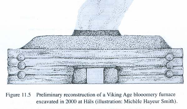
The original proposed furnace layout from
‘Ore, Fire,...’ (1f) Smith had originally proposed an
overall construction consisting of basically a cone of stacked
turf strips, with a cylindrical shaft at least partially clay
lined, all surrounded by a timber framed box, the space between
the cone and the box filled with earth.
From our first considerations of creating a
working furnace based on this design, the small tunnel proposed into
the front wall of the furnace was considered a major problem. There
simply was no space available for any kind of slag control method,
with the exception of use of a slag pit type (not indicated by the
remains). Even for a slag tapping type, this would have to be
physically attempted working down at the end of that restrictive
tunnel, both difficult to accomplish, and likely physcally
hazardous. The required placement of the air blast would have been
functionally too low to the base of the shaft, and also seriously
limiting any attempt to angle the tuyere not alowing for much space
for a developing iron bloom (both of which had proven critical in
numourous smelts).
The archaeology for at least furnaces 4 to 7
indicates a bottom extraction, and again our working experience
suggests attempting this down such a tunnel would prove extremely
difficult (if not impossible). The alternative would be a top
extraction, working down into the shaft while standing on the
earthen platform around the furnace. This however leaves a complete
circular slag bowl, more of an offset ‘bagel’ shape, rather than the
C shapes exposed at Hals.
Providing for a functional working space at the
front side of the furnace thus became a major consideration. This
kind of gap necessitated and indicated by the requirements of slag
control and extraction method as suggested above. Of course it is
certainly quite possible that the first series (remains 1 – 3) were
both constructed and functioned differently than those in the
percieved second series (4 - 7) at Hals.
Our previous test of a full scale, timber framed
and earth packed build suggested there was no advantage, other than
a possible top extraction, to the complete timber box and earth fill
around the basic turf cone. The tools used for adding both ore and
charcoal almost through necessity require long handles to protect
workers from the extreme heat at the top of the furnace. It proved
no problem to simply stand outside the raised box when adding
materials, in fact not having to climb up on to that top surface
every two or three minutes proved a huge advantage. (9)
Although top of the furnace extractions have been
undertaken many times in our past experiments, this method is more
physically punishing to the workers. Even when standing beside a
typical 60 – 70 cm tall furnace shaft, the upper body, and
significantly the face, is exposed to the full heat of the roughly
1100 + C interior. A worker attempting to stand on top of the
proposed earth platform would have the entire body exposed to this
extreme. Additionally, any of the tools required for extraction
(chisels, hooks, tongs) would need to be excessively long to reach
down that extra distance to the bottom of the furnace shaft.
Based on our own working experience, we can see
no advantage to the originally proposed ‘timber frame with earth
fill’ design, and very clear disadvantages.
In addition to these practical considerations,
one critical factor is the raw volume of earth that would be
required to create such a level working platform around a turf cone
built to working shaft height for a functional furnace. With a
typical 65 – 70 cm shaft, and a turf cone at the suggested 200 cm
base diameter, a (very) rough estimate is that some 1.4 cubic metres
of earth fill would be required. (10) This would be thickest deposit
at the outside edges of the framing, certainly not the situation
recored in the excavation diagram.
Clay Body:
Unfortunately, no detailed analysis of the clay
fragments recovered at Hals was ever made. This also includes any
specifics about additions of secondary materials to modify
characteristics to be more suitable for use in furnace construction
(possible sand or organics).
A good sized clay bank was located within a
‘reasonable’ travel distance (about 15 km, considered an ’overnight
walking trip’) by Michelle Hayeur-Smith . (11) It is
unknown if this material does match clay fragments recovered at
Hals.
Working from an analysis and recommendations of
team member Marcus Burnham, taken from his work on the
Icelandic clay sample provided by Hayeur-Smith, we purchased enough
components to match the Icelandic clay, and make up about 45 kg as
dry powdered material. When extended with other additives, this is
enough to construct our proposed furnace and leave a good amount
left over to undertake a second build if required. Based on a
suggestion from Peterson, small batches were prepared and tested to
at least approximate furnace firing temperatures. This overall
experiment is detailed in a separate report - ’Sticking To It - A
clay mix for Icelandic Furnaces’. (12)
The straight Icelandic mix clay body was found to lack the
required structural strength when bone dry, and failed by
melting when heated to 1070 C. (13)
A mix of this clay body with 50% fine sand by weight was
found to remain both structurally strong and also temperature
resistant (to 1070 C). Some cracking was found, but it is known
high sand mixes take extra care in their preparation to avoid
that problem. (It is important to note that this was using an
Ontario source granite based sand, not the basalt type found in
Iceland.)
A mix of dry clay body, sand, shredded horse manure (thirds by
volume) was found to be both structurally strong and temperature
resistant. (This is a mixture that we have long depended on.)
It is our feeling that if the original workers at
Hals were able to utilize this clay, shortage of supply would not
actually be a problem. Depending on details of the build, our
typical free standing ‘Norse Short Shaft’ (f) furnaces require
anything from 30 - 40 litres of prepared clay mixture. Unless clay
was immediately close to hand, the Viking Age gathering method
would certainly have been by ‘the wagon load’.
Phase Three
Our intentions for this, phase three of the overall Hals Icelandic
experimental series:
Make a new consideration of the remains at Hals, considering
what this suggests (to us) about both a detailed furnace build
and smelting method, both individually and as a campaign over
time.
Undertake a full scale, free standing, construction, base on
current understanding. Specifically, will a turf cone alone
provide enough support for the furnace (ie: without the timber
box and earth fill)
Use the same kind of components suggested at Hals - but as
are available locally
Proceed in a measured pace, with full documentation of the
process.
Primary Test 1 : The function of simulated clay body,
based on the best possible duplication of the material
recovered close to Hals.
Primary Test 2 : How does this furnace perform with repairs
and a second firing? In this case most likely the early October
regular smelt date, which will introduce some ‘aging’
observations.
Primary Test 3 : How does a well designed furnace, on the
Hals pattern, endure over time? In this case an overwintering,
with a repeat use 12 months after the original construction.
Long Term Experiment : How will the furnace construction age
over a series of winter freeze and summer rains, ideally
observed over a decade (or more?).
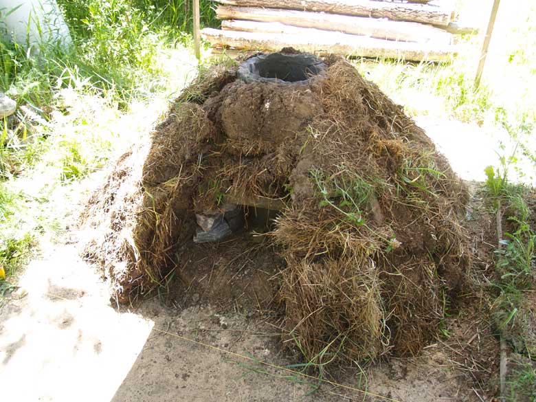
Furnace Build :
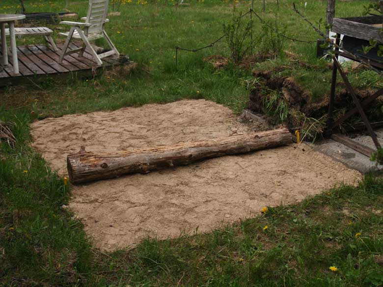
In anticipation of much later examination of the
intended smelt experiments through a process of annual aging, a
clean sand base at 100 by 175 cm had been prepared, cut down below
natural ground level after removing the grass sod (g), to a depth of
about 10 cm below current ground level. One important aspect
here is that no additional framing was required to establish these
clearly straight line edges.
Initial sterile sand pad completed.
Prepared clean sand base area - length of
timber laid at nominal ‘front’ if boxed construction.
It is certainly important to note in the
interpretation seen below, that the overall construction was
primarily taken from furnace 3, while details of the front tuyere
and extraction portions mainly from furnace 7.
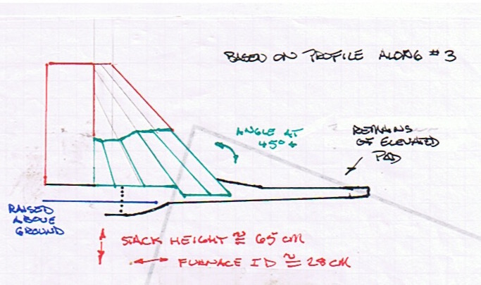
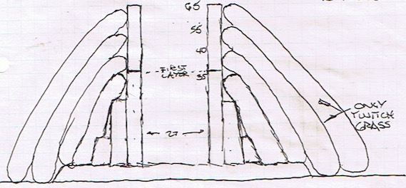
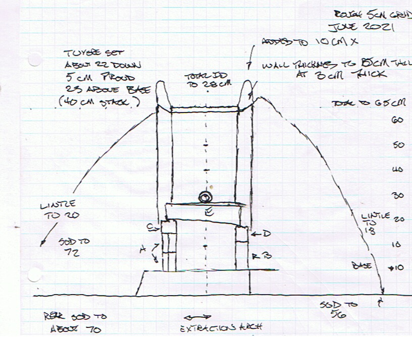
Structures illustrated in original profile,
as a possible working furnace. Background grid roughly 10 cm squares.
To get some concept of the possible original size
and details for furnace 3, the scaled drawing above was prepared.
The slumping into the shaft was straightened to vertical, and the
silt layer corrected to horizontal. The shaft diameter is set to 28
cm, consistent to both the rough dimensions of existing slag bowls 5
/ 6 / 7, and to match a metal form used for many furnace builds in
the past. The lengths of individual turf layers were then mapped on
to this framework, attempting to match both lengths and
tapering thickness. As seen in the profile, the inner three layers
sat on a higher earthen layer than the outer two did. The turf lines
were extended upwards, so the outside layer would remain roughly 10
cm thick at its upper margin. This suggested a total shaft height
(incorrectly labeled ‘stack’ (h) above) estimated at 65 cm. These
measurements would guide the actual construction.
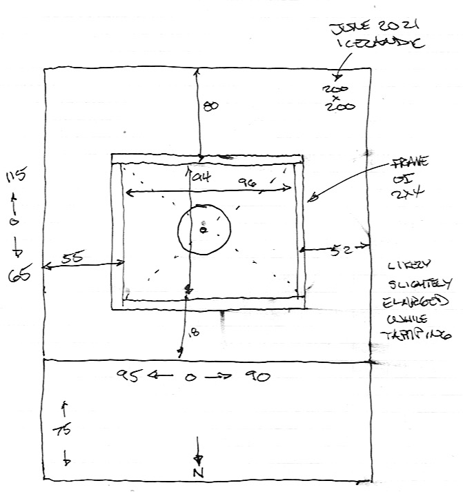
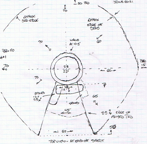
The new furnace construction was placed roughly
centred side to side and slightly to one end on the sand base, to
mimic the overall size suggested by Smith originally, and echoing
the placement of furnace 1. The additional space, located to the
‘front’ of the furnace, would allow for some comparison to the
‘charcoal tongue’ feature recorded in the excavation (seen as light
grey cross hatching to the east / bottom).
Showing the placement of the furnace shaft in
the working area (in cm)
As indicated from the plan drawing, an additional
raised earth pad was created, this of screened ‘dirt’ (to remove
stones via a 1.2 cm grid) laid to a rough depth of 7 cm. This pad
was square during the first part of the build, framed with standard
2 x 4 lumber to ease construction. At this point the dirt pad was 94
cm north to south ( tuyere to rear) and 96 cm east west. This frame
was removed once the lower part of the clay liner had been built up,
and the placing of the first two layers of diagonally stacked sods.
With the frame removed, the earth pad was cut and re-shaped from the
original rectangle to a circular shape.
Based on the clay fire test results, we have decided to construct
the furnace liner of the combination clay / sand / horse manure
mix we have come to depend on. Noted that there is no specific information available from Hals
to support this specific mixture.
As the clay liner had been built thinner and
thinner during earlier experiments, it was found there was a sharp
functional line between 4 and 3 cm thickness, in terms of keeping
clay sticking together to create a wall, and not sticking to hands
and pulling free during the build. This was especially a problem in
experiment 8, where the sod layers were placed first, and the clay
was plastered against the exposed dirt and grass surfaces. For
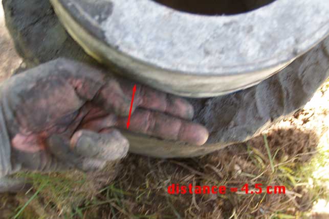
simplicity during this clay build, the walls were constructed using
a ‘two fingers’ guide to allow for consistency. (14) Measured later,
this thickness was 4.5 cm.
During the clay build : ‘two fingers’
thickness.
Much past experience has certainly proved it is
most effective to push slabs of clay against an internal form. The
individual turf layers are then placed against the outside surface
as the liner is built up. The supporting form (depending on type
used) (14) is removed at some point to allow for the expected
shrinking of the clay as it drys. In the past the interior is given
support at this point by the addition of a fill mixture of dry sand
and wood ash. We consider this the most likely overall build
sequence for the furnace itself. If the full timber frame and earth
fill was used, the frame would be constructed after the full sod
cone was established, the earth fill added last.
Positioning of the individual sod layers.
In keeping with the structure indicated by the
profile at Hals, a total of five full layers of sod were laid. There
needed to be an additional small block of sod placed between the
inner most, which was basically vertical to the liner, to create the
start of the desired diagonal lines. The first batch of mixed clay
proved enough to build the liner to 35 cm height.
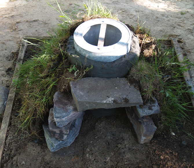
Once the clay was constructed to this level,
provision for the front extraction arch (and possible slag tapping)
had to be made. Working from the excavation diagram and the one
photograph available, a set of individual stones were selected that
most closely resembled the sizes and shapes of those indicated.
These stones were gniess (basalt is not available in Central
Ontario), with fairly flat top and bottom surfaces which made
arranging them much easier. One larger slab was positioned to frame
the open arch created, serving as a needed support for the sod
layers which would be placed above to cover the front wall of the
furnace. This stone would also serve as a the inner support for the
tuyere, to be added later. It should be noted that all these stones
were placed outside the clay liner, and so were not expected to
exposed to much (if any) heat damage effects. This arrangement would
also not allow for any slag from the developing slag bowl to adhere
to the surfaces.
First build level completed 35 cm liner / stones framing arch / 2 layers sod
Once these stones were placed, the first two
layers of supporting sod were positioned. The metal form used to
control the interior diameter is only 40 cm tall, so it was pulled
up and clear. Next the exposed clay interior was filled with the
described sand/ash mixture, primarily for support of the structure.
Once filled, the metal form was re-positioned for the next build
layer, and a second batch of clay mix was prepared. The overall
sequence of steps was repeated, eventually leading to the clay liner
built up to a total of 65 cm shaft height. A third layer of sod was
positioned, then the wooden frame was removed. The earth pad was cut
to conform to the slightly offset circular shape of the sods. Next
the last two layers of sod were laid. The initial build work was
completed by again removing the metal form, and completely filling
the shaft interior with more sand/ash mix. This structure was left
for two days to allow for a first drying phase.
Overall measurements – top view
In this construction, the sods used were loosely
of two different vegetation types, as cut from locations around the
property at Wareham, all to a rough thickness of 10 cm. First was
material composed primarily of what had been originally (some 30
years ago!) commercially available ‘grass sod’. This had been little
maintained, so also included clover and random Ontario weed plants.
This material would form the interior three layers. The outer two
layers were composed of primarily ‘quack’ or ‘twitch’ grass (16),
which has a much different root size and density. The total amount
of cut sods used was roughly 11 square metres.
Build as completed (before air system
installed).
After the time allowed for some drying and
hardening of the clay, the ash sand mix was carefully scooped from
the inside. Some shrinking of the total wall height was obvious, as
well as settling of the sod layers themselves. Using a dry wall saw,
the clay was cut into along the line available by the interior of
the framing stones. This created an available extraction arch
opening 20 cm tall by 23 wide. Although a cut line was created, the
section of clay wall was left completely in place. A smaller opening
was cut into the bottom centre, creating a port for the slag tapping
that was expected to be required. (17) This was a distinctive upside
down U shape, 8 cm tall by 6 cm wide. The clay here was pulled free,
and slightly re-shaped to allow it to be removed or returned as
might be needed.
The total amount of clay mixture used in the
construction of the liner is mathematically calculated as 35 litres
volume. The clay component alone, measured as dry weight, was 19.5
kg. As mentioned earlier, the clay was mixed dry wth equal volumes
(judged by eye) of sand and shredded horse manure, but no specific
measurements of those materials were made separately.
A quantity of timber had been gathered and
prepared, as ‘log’ pieces cut to roughly 2 meters and averaging 10
cm diameter. As well a suitable volume of raw earth had been dug and
bagged, roughly 240 litres total. As discussed, none of this
material was actually used for this specific build.
Some attempt to keep time / labour records was
made. As all this work was undertaken by a single individual,
although well experienced, the time indicated is ‘person hours’. It
should be noted that digging was all undertaken using modern steel
shovels an other tools.
• There was no record made of the cutting and
hauling sod strips.
• Hand shredding the dry horse manure used took
one hour.
• Hand mixing and preparing the clay mixture took
two hours
• The total time for setting the earth pad,
building the clay liner, setting the stone supports and applying the
sod layers, was about 9 hours.
This puts the total build time for this furnace at 13 ‘person
hours’ (importantly, not including gathering materials).
• Although time for digging the earth fill was
recorded, this remains highly dependant on the difficult conditions
at Wareham (soil typically at least 1/3 rock and stone), and this
material was not used.
The next step in preparation was installing a
suitable tuyere and cutting the extraction port and small tapping
arch. As the intent of this experiment was to test the simulated
Icelandic clay mixture, it was decided to use the proven forged
copper tuyere. The possible inclusion of some variation of the blow
hole method, although possibly indicted in the archaeology, was
considered an additional complication at this point in our testing.
Front elevation, showing finished
measurements and tuyere placement
To reduce as much as possible strain on the clay
liner, the heavy copper tuyere was placed so its bottom edge would
rest on the top of the lintel slab. This places the tuyere above the
extraction arch, where our standard is mounting the air input at
right angles to the arch. In keeping with our past experience, the
tuyere was set with an overall downwards angle of 22 degrees and
with the iinner tip placed extending 5 cm proud of the interior
wall. On measuring the distance this placed the tuyere above the
existing hard base of the furnace, this distance was found to be an
acceptable 23 cm. Unfortunately, with the slightly reduced total
shaft height now 63 cm, this allowed for only 40 cm of functional
stack distance. This has come to be considered a bare minimum for
effective ore reduction in furnaces of this size and type. So to
ensure working furnace stack, and to provide a bit of extra against
expected complications, an additional 10 cm of clay wall was added
to the top of the liner. This material would stand well above the
existing line of the diagonal sods however.
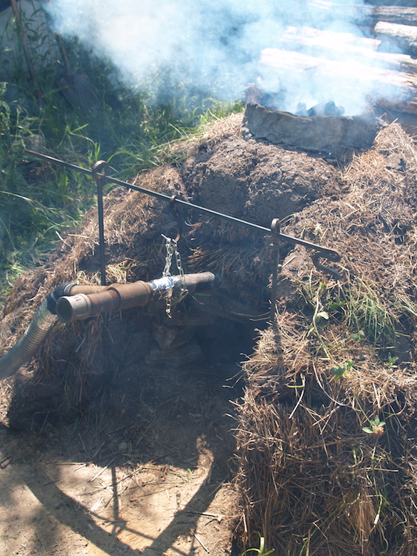
Air system in place, at first addition of
charcoal.
The final connection to the air system was made using our standard
set (obviously modern!) of steel pipe fittings and hose to the
electric blower supplying air. (18) To allow for a clear working
space to the tapping port and extraction arch, these fittings were
hung from a set of steel rods, with uprights located to either side
of the front ‘slot’ in the stacked sods. Although certainly
differing in detail from the Norse use of a human powered bellows
system, it is our feeling that tubes made of heavy leather could
easily allow for the same type of offset to air supply.
Two final elements should be mentioned under this
report on preparation for the smelt itself. Both are considered
deviations from those used at Hals.
Our decision was to proceed with our
standard, proven, DD1 analog mix for ore (Fe2O3 red oxide +
10% flour as binder).
Further, we will continue undertake test smelts
with roughly 25 - 30 kg ore amounts, plus additional
iron rich slag (3 - 5 kg) at the start (to set a working slag
bowl system). This sequence has proven it's effectiveness, and also
if you can make a 3 to 5 kg bloom, you certainly can make an 8 - 10
kg one.
The second variation is the type of charcoal
being utilized. The most likely species used at Hals would be
birch, although it does need to be pointed out that identification
of exact type was never undertaken. The experimental work here has
used commercially available hardwood charcoal, either maple or oak,
as available. For this specific smelt, oak was used. There is a
clear relationship between wood species and charcoal density, the
same volume of oak containing more contributing carbon than the same
volume of (lighter) birch. This suggests that to provide the same
reactive chemistry, a slightly stack height would be required for a
furnace using all birch charcoal. (It must be noted that no specific
experimental tests have been undertaken of this to our knowledge.)
Element
Hals
Wareham
construction
boxed cone ?
cone
clay liner ?
clay liner
shaft ID
25 - 35 cm
28 cm
shaft height
plus 40 ?
70
liner thickness
plus 3 cm
4.5 cm
build
materials
clay
?
local
approximation
additives
?
sand / manure
sand type
basalt
granite
stone
basalt
gniess
grass strips
Icelandic 'turf'
Ontario 'sod'
tuyere
?
copper
air
supply
bellows +?
electric
slag
control
?
tapping
extraction
bottom?
bottom
ore type
source
primary bog
analog
oxide
FeO(OH)
Fe2O3
Fe content
?
55%
silica
?
14%
volume
?
25 kg
charcoal
birch
oak
Comparing Hals to Experiment 9 (Phase 3-A)
Definitions:
a) SLAG BOWL - a dish shaped structure composed primarily of once
melted iron rich slag. This is likely to have a depression where the
iron bloom itself was pulled free, this depression is formed towards
the insertion point of air into the furnace. The slag bowl may have
this side broken away, which is most typical of a bottom side
extraction of the bloom. (This is seen in the remaining slag bowls
excavated at Hals) Some estimate of bloom size can be made by
measuring this depression. The slag bowl will also contain pieces of
charcoal towards the edges and most certainly on the bottom surface.
There are likely to be fragments of reduced iron still remaining,
increasing in concentration towards the bloom side depression.
b) SHAFT - the internal height of a furnace, measured from cleared
bottom level upwards. The shape of the shaft is most typically a
cylinder or a slightly tapering conical section which would narrow
towards the top.
c) TURF - used here specifically to refer to the type of ground
cover existing at Hals. This will be the upper growth surface with
the roots, lifted or cut free of the soil beneath.
d) TAP SLAG - a distinctive, dark black, solid, iron rich slag, very
fluid at temperature. Depending on furnace design and wall
materials, and especially silica content of the iron ore used, large
quantities of this material can be produced. Especially as produced
in the later stages over the course of a working smelt, it is often
necessary to drain off excess levels of liquid slag, to keep from
‘drowning’ the air blast. Commonly, this means poking a hole into
the side of the slag bowl and let the slag run out of the furnace.
This creates either long ‘fingers’, or larger pieces composted of
rounded layers as the slag congeals. These larger layered masses are
referred to as PILLOW SLAG.
f) NORSE SHORT SHAFT – Based on various Viking Age types, a fairly
standard furnace build, typically free standing. Clay or clay mix
material, walls in the range of 7 – 8 cm thick at the base, tapering
to about 5 cm at the top. Normally cylindrical, between 25 – 30 cm
ID, total height between 60 – 70 cm.
See : http://www.warehamforge.ca/ironsmelting/Get-Iron.pdf
g) SOD – Used intentionally here to refer to the form of ground
cover existing at the work location at Central Ontario. Even at
Wareham, two different root structures are created by the
natural ground cover plants, which in turn have
differing physical characteristics. The grass sod material
used for experiments here is not expected to be a good match for the
‘turf’ structure existing at Hals in Iceland (the product of an
extremely different geography and environment).
h) STACK - the internal height of a furnace, measured from the
tuyere (air input) to the top. There is typically some distance
below this to contact possible packing, the slag bowl system, and
sometimes a gap between the top of the bloom and the actual tuyere.
Notes :
1) Smith, K.P., 2005, 'Ore, Fire, Hammer, Sickle: Iron
Production in Viking Age and Early Medieval Iceland', AVISTA
Studies in the History of Medieval Technology, Science, and Art,
Volume 4, USA
Also available as PDF on line :
https://www.academia.edu/191535/Ore_Fire_Hammer_Sickle_Iron_Production_in_Viking_Age_and_Early_Medieval_Iceland
Individual page references :
1a) page 192
1b) page 190
1c) page 190
1d) page 191, measurements via a personal e-mail communication
1e) page 193
1f) page 205
1g) page 190
3) A overview of both the Hals site and these experiments is
currently under preparation, co authored by Smith, Markewitz and
Peterson (‘Now with 70% Less Clay! Experiments with Viking Age
Icelandic Turf walled Iron Smelting Furnaces’) A short video
overview was presented at the recent EAC 12 virtual conference,
available on line : https://youtu.be/7Ltz5NG2BP0
4) The full documentation for each individual experiment can be
found on the web site :
http://www.warehamforge.ca/ironsmelting/index.html
The individual data sets for each of the Icelandic series is colour
coded.
5) Repeatedly over this series, and in conversations related to
Viking Age iron smelting in Iceland, one significant factor has
repeatedly arisen. Markewitz has never been to Iceland. Peterson
has made several visits, but has never been to the actual site at
Hals.
6) A number of experiments in phase one (and additional, non-related
smelts) used this blow hole arrangement, but with a gap between the
tuyere tip and the hole. This team has not experimented with placing
the air tube directly against the exterior furnace wall.
7) Copper tuyeres, forged from heavy plate (.5 cm range) were
introduced to the (North American) iron smelting community by Lee
Sauder about 2005, with the DARC team starting to use one in 2012.
Pure copper melts at roughly 1085 C (depending on alloy), so within
the operating temperature range of an iron smelting furnace. The
radiation effect mentioned is crucial, but with the outside surface
exposed to open air, there is virtually no erosion effect to the
heavy copper, even over dozens of smelt cycles.
The melting point of wrought iron is higher, at 1540 C (although the
functional ‘burning’ temperature in an air blast is significantly
lower). Sauder once again has pioneered the forging and use of a
tuyere made of this material for smelting furnaces. To date, with
less tests described, a wrought iron tuyere appears to suffer some
damage through a full smelting cycle, but certainly has been found
to be robust enough to provide good duration of use. (Note
that the DARC team has not worked with a wrought iron tuyere.)
See :
https://s3.amazonaws.com/images.icompendium.com/sites/eliz2406/sup/3696376-Wrought-Iron-Tuyere-report.pdf
8) It is well understood that the ‘bog ore analog’ material that is
used for this experimental work is only at best ‘approximately’ like
the primary bog iron ore (FeO-OH) recovered at Hals :
- Fe2O3 oxide (Spanish Red) with 10% flour binder
- Typically about 55 % iron content overall.
- Silica content of about 14 %
The typical practice, throughout ancient Northern European iron
smelting, was to pre-roast natural bog iron ores, a process that
would convert the oxide form overall into Fe2O3, and evidence of
this process was found at Hals. (1g) Again it needs to be remembered
that an actual analysis of the iron ore utilized at Hals was not
possible to have been made originally. A consideration of comparing
elemental iron content to other ‘reported’ Icelandic primary bog
ores can be found :
https://warehamforgeblog.blogspot.com/2021/01/truth-in-reporting-sample-iron-content.html
10) Rough estimate based on :
• 200 x 200 cm outside dimension
• earth fill to 65 cm
• less 13% for access gap, based on June 2021
build measurements https://www.calculator.net/volume-calculator.html
11) Information provided over a long duration series of e-mail
communications between Kevin Smith, Michelle Hayeur-Smith, Neil
Peterson and myself.
13) Both theoretical, practical and past measurements have
documented that working temperatures within a functioning iron
smelting furnace will certainly reach 1150 – 1250 C. Temperatures in
excess of 1350 C have been recorded. The use of testing only to 1070
was a restriction created by the top temperature of the propane
forge used for the heating here.
15) When constructing free standing clay furnaces, most typical
builds have tapering walls, thicker at the base for additional
support of the thinner upper sections. The standard build is 7 – 8
cm thick at the base, tapering to 5 cm at the top. In discussions,
Peterson pointed out that there was no particular reason why the
clay walls needed to be uniform in thickness in cross section. What
he suggested is building so the interior diameter was slightly
offset to the exterior, creating a thicker front wall, at the
tuyere, than at the rear section. This would provide for the known
erosion effect of the hottest part of the furnace, in the past
normally seen as an oval shape, extending 10 cm to ether side of the
tuyere, 8 – 10 cm below that point, and reaching upwards about 15
cm.
This proposed design has yet to be field tested.
16) This is an extremely aggressive, initially invasive, species
found throughout Canada. It has thick roots, but more widely spaced,
which quickly choke out other plants once established. One clear
difference is that a cut strip of twitch grass will not hold
together if picked up from one edge, so the individual sods do not
retain the same relative structural strength when applied as a
building material as was the case here. (see also definitions c and
g above)
http://www.omafra.gov.on.ca/english/crops/facts/quackgrass.htm
17) It is unknown what, if any, silica (as sand) might have been
present in the natural bog iron ore available and used at Hals.
Since the slag is composed of silica from the ore and melted inner
walls, obviously our test may not closely resemble the volume of
slag generated by the Norse, and thus the whole dynamics of slag
control. From past repeated use of our DD1 analog, it was fully
expected that slag tapping would be required.
18) The whole question of how well any electric blower system can
simulate probable Viking Age bellows produced air is considered an
entirely separate area of investigation. Although a number of
potential Norse style bellows have been tested in past experiments,
these all require a considerable number of additional workers,
beyond the smelt team itself, to operate effectively. See ‘An
Iron Smelt in Vinland’ : http://www.warehamforge.ca/ironsmelting/LAM/Smelting-Vinland-V3.pdf