Archaeology, Experience and Experiment :
Further tests of Icelandic iron smelting furnaces
Darrell Markewitz, with contributions by Neil Peterson and Rey Cogswell
Abstract
In 2021, a re-evaluation based
on the available descriptions of the Viking Age bloomery iron
smelting site at Háls in Iceland was made by a team of
independent researchers from Ontario, Canada. This new
assessment was largely focused on what had been learned from
eight previous experimental tests, plus the considerable
smelting experience gained since this specific project was
started in 2007. Two additional smelt events were then
undertaken, one in June and one in September of 2021. This paper
will detail this process, report the results, and illustrate how
archaeological evidence was interpreted through practised skills
into functioning experiments.
Author's Note :
Experimental Background
Starting in 2007, a small group of independent researchers undertook an experimental investigation guided by the archaeology of a Viking Age bloomery iron smelting site located at Háls in Iceland. Descriptions of this site were presented by Kevin P. Smith in his paper Ore, Fire, Hammer, Sickle: Iron Production in Viking Age and Early Medieval Iceland (Smith 2005). The team, drawn from members of the Dark Ages Re-Creation Company from Ontario, Canada, was lead by the primary author, and had a long professional and personal relationship with Smith.
This series started with the preparation of a concept overview, attempting to match a theoretical furnace design proposed by Smith into a functional system. (Markewitz, 2008) The planned experimental work would physically test how various elements would work individually and then finally into a functional whole, of that proposed furnace layout. There were a total of eight furnace builds and full smelt cycles, that can loosely be broken down into two phases :
Phase One / four experiments / 2007 and 2008 / testing individual design elements
Phase Two / four experiments / 2012 to 2016 / testing use of turf builds, then adding proven elements from Phase 1
In 2021, it was decided to return to work on the Háls system, as a number of major questions remained unanswered. An important factor would be re-evaluating the archaeological evidence, in light of significantly more practical experience with small scale direct process bloomery furnaces that had been acquired since this series started (over 60 additional smelts).
The intentions for Phase Three of the overall Háls Icelandic
experimental series:
Re-Evaluating Háls
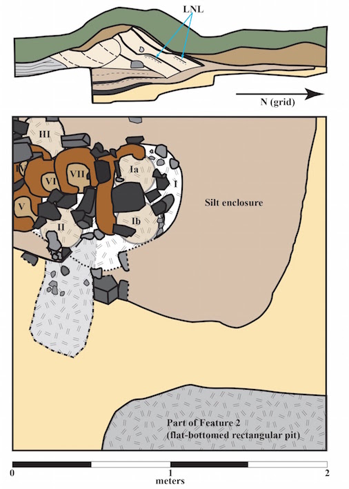
Háls is located in Mid-Western Iceland.(Smith, 2005) The number of furnace bases and large size of the associated slag piles all suggest an 'industrial' operation, with many firings over an extended period of time. Use date can be estimated from a volcanic ash layer within the turf blocks used in furnace construction which was deposited in the early 870's, Smith suggests smelting activity dated to the 870's to mid 950's, with two separate 'campaigns' of use. (Smith, 2005) The original excavations exposed a number of furnace bases, four with slag bowls from their last use still in place. Additionally the excavation process exposed a cross section along the edge of one furnace. (1)
Figure1: “ Stacked furnace bases (Ia - VII) within a silt and turf enclosure (Feature 1) excavated in 2000 at the Viking Age iron production complex (Háls 5-6) at the site of Háls, Kollslækur, Borgarbyggð, western Iceland."
" Slag rims (dark brown) and slag bases (light brown), fire-damaged rocks (dark gray) and rocks without evident fire damage (light gray) are shown in the plan view at bottom with hache-marks identifying areas of charcoal staining and charcoal concentrations.
" Profile drawing of the western wall of the excavation unit, at top, shows from base to surface: undisturbed, pre-occupation sediments (yellow); silt from rebuilt enclosures surrounding the furnace bases (beige); charcoal and slag lenses (black); slanting turf blocks from furnace stack construction (light beige) with couplets of the "landnám tephra (877±1 AD) shown inside the cut turf blocks; cross section through the edge of furnace III (gray); sediments from post-iron-production agricultural activities (ca. 1000-1250 AD) at the site (brown); and the rooted modern surface soil (green).”The furnace cross section shows layers of cut turf strips, roughly 10 cm thick, laid diagonally.
Two more or less straight lines, cut slightly into the base ground level, and silt filled, bracket the furnace area.
Four furnaces are built close to, and set slightly over top of, each other.
Slag bowls are 25 – 35 cm diameter (indicating the interior furnace dimension).
Slag bowls have an overall C shape (indicating a bottom, side extraction method). (Markewitz, 2008)
A triangular area of ash, charcoal and slag fragments leads off from one side of the grouped furnaces (indicating an open working area there, and again typical of bottom extraction).
A number of small sized stones, marked with slag, were found close to the furnace base on this side (suggesting framing and support of a tapping / extraction arch)
There were no clay / ceramic wall remains at the furnaces themselves.
Broken vitrified clay fragments, up to 3 cm thick, were recovered from the slag piles (suggesting at least a minimum clay liner thickness), some with slag on one (inner?) surface.
There were no ceramic tuyere fragments recovered, or are known from Iceland.
Locally available primary bog iron ore was used.
Charcoal used is primarily birch, again locally available.
Most unfortunately, further archaeological investigations of this site were not possible. Importantly to this discussion, chemical analysis of the ore used, the slag remaining, or the clay recovered, could not be made.
Matching Clay
The major question about Háls is why the distinctive furnace construction (turf cone possibly supporting a thin clay liner) was used. Access to clay, a standard building material for bloomery furnaces, is problematic for Iceland, where true clays are both uncommon, and where available, limited in volume. Key understanding why this construction method was employed are the characteristics of the clay that was used. As has already been stated, no detailed analysis of the actual clay fragments recovered was available. This also included any specifics about possible additions of secondary materials (temper) to modify the base characteristics to be more suitable for use in furnace construction (possible sand or organics).
Importantly, a good sized clay bank had been located within a ‘reasonable’ travel distance (about 15 km, considered an ’overnight walking trip’) by Michelle Hayeur-Smith.(2) A sample of that clay was made available, but it is unknown if this material does in fact match the clay fragments recovered at Háls. This sample was analyzed by team member Marcus Burnham, a professional geologist.
| Result type | Average | Mixture |
| SiO2 | 47.61 | 51.63 |
| TiO2 | 2.24 | 0.03 |
| Al2O3 | 13.44 | 13.81 |
| Cr2O3 | 0.02 | 0 |
| Fe2O3 | 13.14 | 13.1 |
| MnO | 0.21 | 0 |
| MgO | 5.63 | 5.81 |
| CaO | 9.1 | 9.08 |
| BaO | 0.01 | 0 |
| Na2O | 2.08 | 1.36 |
| K2O | 0.8 | 0 |
| P2O5 | 0.3 | 0 |
| SO3 | -0.07 | 0 |
| Other | 0 | 0.57 |
| LOI (volatiles) | 5.23 | 4.58 |
| Sum Of Conc. | 99.74 | 99.98 |
Based on
recommendations by Burham, the following components were purchased
from a commercial pottery supplier to create about 45 kg dry
weight of a simulated ‘Icelandic’ clay :
| Bentonite | 22.7 kg |
| Mullite Grog | 2.3 kg |
| Talc (Amal C-98) | 6.8 kg |
| Wollastonite | 7.7 kg |
| Black Iron Oxide | 5.0 kg |
Table B : Commercial Components for simulated clay.
The dry clay components were blended using a mechanical cement mixer. Small batches with differing additives were hydrated to plastic, pressed into 4.5 cm diameter by 10 cm long cylinders, then dried and heated to at least approximate furnace firing temperatures (1070 C)in a propane forge. (3)
The straight Icelandic mix clay body was found to lack the required structural strength when bone dry, and failed by melting.
A mix of this clay body with 50% fine sand by weight was found to remain both structurally strong and also temperature resistant. Some cracking was found, but it is known high sand mixes take extra care in their preparation to avoid that problem.
A mix of dry clay body, course sand, and dry shredded horse manure (thirds by volume) was found to be both structurally strong and temperature resistant. (This is a mixture that this team had developed, and has long depended on.)
The furnace built for these experiments used approximately 19.5 kg (dry) of the ‘Icelandic’ clay. If the original workers at Háls were able to utilize the clay bank located by Hayeur-Smith, shortage of supply should not actually have been a problem, as unless clay was immediately close to hand, the Viking Age gathering method would certainly have been by ‘the wagon load’.
Based on the firing tests, and considerable previous experience, the dry thirds of clay / sand / dry manure mix was used for the furnace construction. Two points should be noted :
It remains unknown what, if any, tempering additives were employed at Háls.
The sand used was Ontario, granite based (72 % silica), rather than the Icelandic, basalt based (45-52 % silica) type. (Geology Science, 2018) It is unknown if this would have a significant effect.
The sand used was dug from a local natural deposit. This was screened using a 6 mm grid to remove stones, individual particles varied considerably (inclusion of limestone pebbles). The horse manure was gathered from a neighbour’s farm, selecting well dried ‘pucks’ that had been aging for a considerable time. These were shredded by rubbing between the hands. The proportionsof dry clay / sand / manure were estimated by eye, then hand mixed to blend uniformly. Water was added to create the desired plasticity, attempting to keep the batch uniform and to a consistency known to be suitable based on past building experience. The material was prepared in two separate batches, so some variation in moisture content would be expected between batches. A very approximate measurement was made of volumes used, with roughly 10 litres each of dry clay, sand and manure, mixed with about 10 litres of water, per batch.
Timber Framing?
The diagonal stacking of turf exposed at Háls certainly suggested an alternative to a self supporting thick clay furnace, instead using a main cone shaped structure built of turf with only a relatively thin fire proofing layer of clay. Smith had further proposed that this structural cone was surrounded by a timber box, with the space between filled with earth to create a flat upper working surface. (Smith, 2005, p. 192)
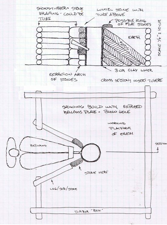
Figure 2 : The 2007 interpretation of the
furnace construction, modified for improved function,
based on Smith's original concept)
Our previous test of a full scale, timber
framed and earth packed build (October 2016) suggested there was
no advantage to this build. The tools used for adding both ore and
charcoal almost through necessity require long handles to protect
workers from the extreme heat at the top of the furnace. In
practice, it proved no problem to simply stand outside the raised
box when adding materials to the furnace, something that is
required every two or three minutes.
One possible reason for a flat upper surface
would be if undertaking a top extraction, working down into the
shaft while standing on the earthen platform around the furnace.
Past experience with top extraction methods has clearly
demonstrated how physically punishing this method is for the
workers involved. Even when standing beside a typical 60 – 70 cm
tall furnace shaft, where the legs are partially protected by the
walls, the upper body, and significantly the face, is exposed to
the full heat of the roughly 1100 + C interior. A worker
attempting to stand on top of the proposed earth platform would
have the entire body exposed to this extreme, even if the face
would be further removed. Also, any of the iron tools required for
extraction (chisels, hooks, tongs) would need to be excessively
long to reach down that extra distance to the bottom of the
furnace shaft.
Although suitable timber and quantity of earth had been gathered in preparation for the Phase 3 furnace construction, in the end it was decided to test a build using only the sod cone structure, without any additional framing.
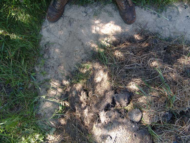
As a quantity of cut grass sods (see discussion below) would be needed, the first location where these where cut was a 200 by 275 cm area where the furnace was to be located, stripped to a depth of about 10 cm. In anticipation of much later examination of the furnace through a process of annual aging, a clean sand base was created by simply filling the space where this sod was removed. One important aspect here is that no additional framing was required to establish the clear straight line edges from were the sod strips were removed. This is considered reflective of the roughly straight edges exposed at Háls, which were found to be composed of a layer of deposited material extending downwards roughly 5 cm at the edges. (Smith 2005, page 204 / see figure 1)
Building with Sod
In this experimental series overall, a clear
distinction is being made between Icelandic turf and
Ontario sod. In both cases, what is being referred to is a
strip cut from the uppermost natural growth layer, to a depth
where the root system of the vegetation has penetrated and able to
hold a thickness of the underlaying dirt in place. Smith indicated
that the individual turf strips exposed at Háls had an average
thickness of 10 cm. (Smith, pers. comms) There are significant
differences between the natural environments of Iceland and
Central Ontario, and this clearly has an impact on the qualities
of both the soils and vegetation. Grass sod is used
intentionally here to refer to the form of ground cover existing
at the work location at Wareham, which is not expected to be an
identical match for the turf structure existing at Háls in
Iceland. (4)
In this construction, the sods used were
loosely of two different vegetation types, as cut from various
locations around the property at Wareham, all to a rough thickness
of 10 cm. First was material composed primarily of what had
originally been (some 30 years ago!) been commercially available
‘grass sod’ strips, placed over a thin layer of topsoil, in turn
over fill composed of a mix of sand, clay soil, and (many!)
stones. This lawn grass had never been maintained, so also
included clover and random Ontario weed plants. Strips of this
material would form the interior three layers of the structure.
The outer two layers were strips composed of primarily Quack Grass
(Elymus repens), which has a much different root size and
density (larger roots, but fewer of them).
In interpreting the archaeology at Háls into the test furnace used for Phase Three, the overall construction was primarily taken from furnace III, while details of the front tuyere and extraction portions mainly from furnace VII.
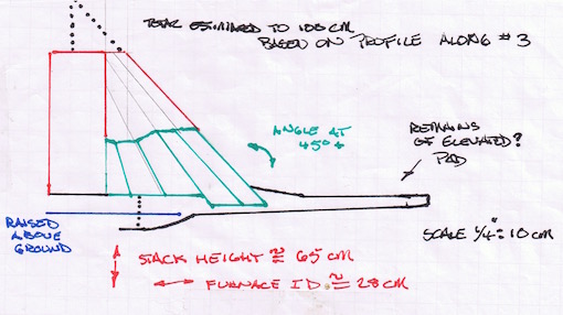
Figure 3 : Structure from the cross section of
furnace III, reconstructed into a possible working furnace.
(Roughly placed on a 10 cm grid.)
To get some concept of the possible original
size and details for furnace III, the scaled drawing above was
prepared. The slumping into the shaft is seen straightened to
vertical, and the lower silt layer corrected to horizontal. The
shaft diameter isset to 28 cm, consistent to both the rough
dimensions of existing slag bowls Háls 5 / 6 / 7. The lengths of
individual turf layers were then mappedon to this framework,
attempting to match both length and tapering thickness as recorded
in the excavation cross section. As seen in the original profile,
the inner three layers sat on a higher earthen layer than the
outer two did. The turf lines were then extended upwards, so the
outside layer would remain roughly 10 cm thick at its upper
margin. This suggested a total shaft height estimated at 65 cm, a
height considered functional based on previous experiments. These
measurements would guide the actual construction.
The test furnace was placed roughly centred
side to side and slightly to one end of the prepared sand work
space to mimic the overall placement suggested by Smith
originally, and echoing the placement of furnace I. The additional
space, located to the ‘front’ of the furnace, would allow for some
comparison to the ‘charcoal tongue’ feature recorded in the
excavation plan.
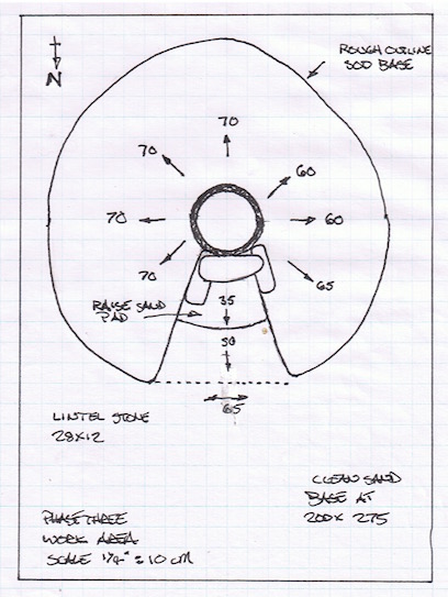
Figure 4 : Plan view, showing the placement of the furnace shaft in the working area.
As indicated in figure 4, an additional raised
earth pad was created, this of dirt screened to remove stones (via
a 1.2 cm grid) laid to a rough depth of 7 cm. This pad was square
during the first part of the build, held to place with a frame of
standard 2 x 4 lumber to ease construction. At that point the dirt
pad was 94 cm north to south ( tuyere to rear) and 96 cm east
west. Once the lower part of the clay liner had been built up, and
the first two layers of diagonally stacked sods were placed, this
frame was removed. Next the earth pad was cut to a circular shape.
In keeping with the structure indicated by the
profile at Háls, a total of five full layers of sod were laid.
There needed to be an additional small block of sod placed inner
most and basically vertical to the liner, to create the start of
the desired diagonal lines. T The individual sod strips had been
cut as rectangles, roughly 20 cm long by 50 – 75 long, and were
placed with their top edge against the outside surface of the
inner clay liner as that was built upwards. To generate the
required conical shape, pieces were cut into various triangular
shapes and lengths to fill the gaps. The resulting structure was
slightly irregular, and had base measurements of roughly 70 cm to
either side and a total 160 cm front (tuyere side) to back. The
total amount of cut sods used was roughly 11 square metres, a
volume of roughly 1.1 cubic metres.
If the full timber frame and earth fill had
been used, the frame would be constructed after the full sod cone
was established, then the earth fill added last.
Building with Clay
One aspect that had been tested through the
Phase Two builds was a steady decrease in the thickness of clay
liner walls. The construction sequence had been to stack up a
number of layers grass sod to a height of roughly 30 cm, leaving a
cylindrical hole in the centre. The sides of this hole would then
be plastered with clay mix. This process was repeated at least
twice, allowing for building upwards sufficiently to create the
required shaft height (typically 60 cm). As the clay layers were
reduced in thickness with individual builds, it became more and
more difficult to get the clay to remain in place against the
loose earth edges of the sod layers. The failure point was found
to be between 4 to 3 cm thickness.
One solution proposed to the ‘sticking to the
sod’ problem was to reverse the order of the layering during
construction. The clay walls would be built up against an internal
form, then the sod laid against this liner as the furnace was
built higher. Use of a form allowed control of both the internal
diameter and overall shape. (5)
During the Viking Age, there would be a number of ways of doing this :
A simple bundle of twigs or grasses, which would be burned away as part of the drying or pre-heat phase. There are certain advantages to this supporting method, both ease and allowing for flexibility as the clay shrinks as it drys (depending on material used). This same flexibility does mean that creating a regular circular cross section requires more care as the walls are built up. Depending on the size of the individual pieces of vegetation, there may be a noticeable corrugated inner impression to the clay as it is pressed inwards. The overall shape of the resulting furnace is more likely to be conical rather than cylindrical. The small fragments of clay recovered at Háls do not allow for either of these indications to be visible.
A wicker ‘basket’, either cylindrical or conical. Again, use of a woven form is likely to create distinctive impressions on the soft clay as it was applied. If used as an external form, it would have to remain in place between clay and sod layers, and would create difficulty when working down inside the narrow shaft. If used as an interior form, it would need to remain in place through the entire drying process. When this specific method was tested (June 2019) it was found that a tight wicker basket did not allow the drying clay to shrink, resulting in significant cracking of the walls (6)
A wooden stave built form, either cylindrical or slightly conical. By holding the staves together with rope, it would be easy to pull the individual staves free to remove them at the start of the drying process. This would allow for re-use of this form and so standardization of furnace size, an important consideration for a multiple smelt ‘industrial’ operation. Individual staves could be either flat or shaped to slight curves, a choice that should leave indications on the clay. To limit clay from sticking to the wooden surface, ideally there would be a separating layer, which could have been either a piece of cloth or birch bark, which might create impressions of the separating material used. Again, the small fragments remaining at Háls would be unlikely to indicate much. One difference with the use of a rigid form is that it needs to be removed as the clay starts to dry and shrink, again to prevent cracking.
For the Phase Three furnace, a standard
cylindrical sheet metal form was used. This was covered with
two layers of newsprint as a separator. The form was 28 cm ID, and
40 cm tall, the top fitted with a handle to make removal easier.
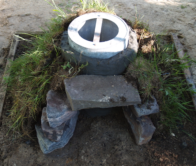
Figure 5 : First clay build completed to 35 cm,
stones placed for the extraction arch,
with two layers of sod stacked to support.
Once these stones were placed, the first two
layers of supporting sod were positioned. The metal form used to
control the interior diameter was then pulled up and removed. Any
major flaws in blending over the clay surface revealed were
repaired, then the interior was filled with a dry mixture of
roughly 50 / 50 sand and wood ash. This fill would both support
the clay structure, but also serves help pull moisture out of the
damp walls. The metal form was re-positioned for the next build
layer. The overall sequence of mixing and construction steps was
then repeated, eventually leading to the clay liner built up to a
total of 65 cm shaft height. On completion of the full clay liner,
the remaining layers of sod were placed, to a finial height of 65
cm.
After allowing the clay to dry and harden for
two days, the ash sand mix was carefully scooped from the inside.
Some shrinking of the total wall height was obvious, as well as
settling of the sod layers themselves. Using a dry wall saw, the
clay was cut along the line available by the interior spacing of
the framing stones. This created an available extraction arch
opening 20 cm tall by 23 wide. Although a cut line was made, this
section of clay wall was left completely in place. A smaller
opening was cut into the bottom centre, creating a port for the
slag tapping that was expected to be required. (7) This was a
distinctive upside down U shape, 8 cm tall by 6 cm wide. The clay
here was pulled free, and slightly re-shaped to allow it to be
removed or replaced as might be needed.
After the tuyere was installed (discussion
below), the distance of tuyere tip centre above the existing hard
base of the furnace was found to be an acceptable 23 cm.
Unfortunately, with the slightly reduced total shaft * height now
63 cm, this also allowed for only 40 cm of functional stack *
distance. This has come to be considered a bare minimum for
effective ore reduction in furnaces of this size and type. To
ensure a working furnace stack, and to provide a bit of extra
against expected complications, an additional 10 cm of clay wall
was added to the top of the liner (so creating a stack height of
50 cm) This extra material would stand well above the existing
line of the diagonal sods however.
* Shaft is defined as distance from
ground level to top of furnace.
Stack is defined as distance from centre of
tuyere tip to top of furnace.
(Markewitz, 2021B)
Tuyeres
A critical element to effective furnace
operation are the dynamics of air supply. Within the archaeology
of Viking Age Iceland there has been nothing recovered indicating
directly the use of ceramic, copper alloy or iron tuyere tubes.
(Smith, 2005, pg. 191)
Tuyeres inserted through furnace walls are all
subjected to the full internal temperatures during smelting. Clay
tubes will sinter into (relatively) durable ceramic, at least on
the furnace ends, further subjected to visible heat erosion
effects, and thus can be found archaeologically (Pliener, 2000).
Heavy walled copper tuyeres have been long used by this team, and
have been found to have almost no damage effects over many smelts.
Outside a possible archaeological recovery of what would certainly
have been an ‘expensive’ and multiple use piece of equipment, a
copper tuyere is unlikely to leave any visible signs. (8) A third
possibility would be a very thick walled forged iron tuyere.
Although some recent tests have been undertaken using this type,
limited information is available on what signatures might remain.
(Sauder, 2020.)
The only remains found at Háls suggestive of
the air supply system was a single clay fragment suggesting “... a
circular, vitrified opening ...” (Smith, 2005, pg 191) which was
later described as indicating a 5 – 6 cm diameter. (Smith, pers.
Comm.)This potentially could be clay initially packed around an
insert type tuyere, but later allowing hot gasses to escape.
Alternately the fragment could be the opening for some variation
of the ‘blow hole’ method (where the air supply tube is placed
just touching, even proud of, a hole cut into the furnace wall).
This arrangement would not create any significant damage to metal
or ceramic tuyeres, and might even allow the use of bone, possibly
even wood, tubes. With past test uses of a blow hole (Phase Two
and others), there has been found to be a serious impact on air
penetration into the furnace, in turn changing the dynamics of how
heat locates in the furnace. This results in higher, shallower,
slag bowls, typically only extending part way across the furnace
diameter, requiring more careful slag management (so frequent
draining / tapping). More heat washes back on to the wall surface
around and above the insertion point, creating more damage to
those surfaces. With a reduced size slag bowls also comes smaller
blooms. It needs to be remembered that any variation of the blow
hole system requires a fully exposed and self supporting front
furnace wall section, which would necessitate thicker clay walls,
at least in this area.
There is an advantage to placing any solid
tuyere tube so it rests on top of a lintel stone, both to maintain
position and the weight. It wouldalso be possible to mount tuyere
tube directly through a stack of turf. The turf layers would
certainly be less stable, and are likely to result in shifting of
at least entry angle over the course of the smelt. Also any metal
tuyeres rely on freely exposed surfaces to radiate off excessive
heat, thus keeping their interior portions from melting. At the
very least, the depth of surrounding (and insulating) turf would
have to be limited as much as possible.
The use of some variation of the blow hole
method, although possibly indicted in the archaeology, was
considered an additional complication at this point in theseries.
As the intent of this experiment was to test the simulated
Icelandic clay mixture, it was decided to use a long proven
forged copper tuyere. The total length is 45 cm, the size
tapering from 5 cm ID at 3 mm walls at the air supply end to 2 cm
ID at 6 mm thick on the furnace end, with a weight of 3.4 kg.
To reduce as much as possible strain on the
clay liner, the heavy copper tuyere was placed so its bottom edge
would rest on the top of the lintel slab. This placed the tuyere
above the extraction arch, instead of our standard mounting of the
air input at right angles to the arch. In keeping with our past
experience, the tuyere was set with an overall downwards angle of
22 degrees and with the inner tip placed extending 5 cm beyond the
interior wall.
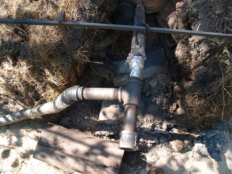
The final connection to the air system was made
using a set of steel pipe fittings and hose linking to ahigh
volume electric blower supplying air. (9) To allow for a clear
access to the tapping port and extraction arch, these fittings
were hung from a set of steel rods, with uprights located to
either side of the front ‘slot’ in the stacked sods. Although
certainly differing in detail from the Norse use of a human
powered bellows system, it is our feeling that tubes made of heavy
leather hung from wooden poles could easily allow for the same
type of required offset to the air supply.
Ore and Charcoal
Icelanders have utilized locally available
primary bog iron ore over their history. The exact iron oxide,
silica (as sand), and other components will vary by deposition
type and environmental factors, not only between specific
locations, but also over time. Although traces are found across
Iceland, finding a deposit large enough, and with a high enough
iron (FeOOH) content to allow for useful exploitation in direct
process bloomery furnaces is based on chance. The amount of silica
present directly impacts on the amount of slag formed, which may
be significant to understanding the process at Hals, where less
evidence of tap slag has been found.
Importantly to these experiments, there are no
naturally occurring bog ores within several hundred kilometres
travel of the test location in Ontario. Starting with the
‘Vinland’ series in 2008, a suitable ‘bog ore analog’, had been
developed, originally based on the fragments of ore recovered
during excavations at L’Anse aux Meadows, Newfoundland.
(Markewitz, 2014)
Our decision was to proceed with our well
proven, DD1 analog mix as ore (commericial Fe2O3 red oxide
+ 10% whole wheat flour as binder, at 53% iron content).This is
mixed as dry powder, then water is added to create a paste like
consistency. This is then spread on shallow trays and allowed to
sun dry before collecting. As with the early phases, these tests
would continue using roughly 25 kg ore amounts per smelt.
In addition, an initial amount of iron rich tap slag was added
as broken pieces. It has been proven over a large number of
earlier smelts that this sequence will quickly establish a working
slag bowl system, speeding the formation of the metallic bloom and
also resulting in increased overall yield. The exact size of the
blooms produced at Háls remains unknown, but it was considered
that the 3 to 5 kg blooms normally expected from this combination
would certainly prove the basic effectiveness of the smelting
furnace and sequence employed.
The second variation of materials was the type
of charcoal to be utilized. The most likely species used at Háls
would be birch, although it does need to be pointed out that
identification of the exact type was never undertaken. The
experimental work at Wareham has used commercial hardwood
charcoal, either maple or oak, as available. For these specific
smelts, white oak charcoal was used. There is a clear
relationship between wood species and charcoal density, the same
volume of oak containing more contributing carbon than the same
volume of less dense birch. This suggests that to provide the same
reactive chemistry, a slightly taller stack height would be
required for a furnace using all birch charcoal. (It must be noted
that it is unknown if any specifically documented experimental
tests have been undertaken to measure this.)
Smelting Sequence
A fairly standard sequence was undertaken both times. A period of pre-heat with wood splits is followed by filling the furnace with rough charcoal. As the interior fully ignited, this is changed to graded fuel, broken and screened to pieces ranging from .5 to 2.5 cm. Charcoal is measured using a standard ‘bucket’, roughly 1.8 kg, (later one ‘bucket full’ is weighed to calculate the total amount consumed). This is added to the furnace as the top level has dropped roughly 5 cm, about 500 gms per addition. Once the entire charcoal column has fully ignited, air volume is adjusted to set what was considered a suitable burn rate, typically aiming for a rate of 8 to 12 minutes per bucket. Slag charges were added first, followed by first charges of ore. Slag and ore is pre-measured by weight, and those amounts added evenly through each of the quarter charcoal bucket units. As the reaction progresses, individual ore charges are increased, normally reaching between 2 - 3 kg per charcoal measure. Slag is tapped as required to ensure the air blast remained clear, primarily determined by changes in sound, but also by observing the tuyere tip via a glass view port. Once all available ore is added, additional charcoal is added to ensure all the reduced ore is deposited onto the bloom, then the remaining charcoal allowed to burn down to close to tuyere level. At this point the bottom arch is opened and the bloom mass is broken free of the slag bowl and extracted. The mass is then hammered with multiple sledge hammers through a single ‘heat’ cycle to knock off clinging slag and partially compress the bloom. Final weight is taken afterwards. (10) Use of a standard method is considered important, as it allows comparisons between previous experiments.
Smelt A – June 20, 2021
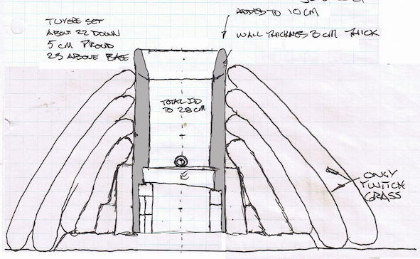
Figure 6 : Front elevation of completed furnace, ready for experiment A
Details :
Wall Thickness : 4.5 cm
Interior Diameter : 28 cm
Total Shaft Height : 70 + cm
Grass Sod Exterior : 5 layers stacked, average diameter beyond liner at 60 cm, height at 65 cm
Extraction Arch : stone framed, cut through liner at 23 cm wide by 20 cm tall
Tapping Port : 6 cm wide by 8 cm tall
Tuyere : forged copper, set 5 cm beyond interior wall, 22 degrees down angle, placed above extraction arch
Stack Height (above tuyere) : 50 cm
Base Depth : 29 cm above hard base, charcoal fines layer adjusts depth below tuyere to 15 cm
Preheat Phase : 60 minutes
Air Volume : 800 Litres/minute (estimated, see ‘Air Rates’)
Total Slag Added : 5 kg
Total Ore Added : 25.5 kg
Total Charcoal Consumed : 69 kg (‘bucket’ = 1.8 kg)
Primary Sequence (over ore additions) : 295 minutes
Primary Charcoal Burn Rate : (average over ore additions) 8.7 minutes / kg
Ore Rate : (average over additions) 11.6 minutes / kg
This smelt generally ran as was expected. The one modification from standard practice was the use of a slightly lower air volume, set intentionally to more closely mimimic amounts possible through the use of human powered bellows systems. This substantially increased the burn time per kilogram (where something closer to 4 – 5 minutes is considered more ideal). The most obvious impact of this reduced air flow was that the slag bowl initially developed too high and potentially too close to the tuyere side of the furnace. This necessitated an early tap to prevent ‘drowning’ the air blast. Shortly into the addition of ore charges, some of the lower charcoal fines were scraped out, allowing tapped slag to flow below the bottom of the existing bowl. This method has been found to soften the bottom of a slag bowl, allowing it to slump downwards, in effect lowering the entire complex so as to leave more space both for the accumulating liquid slag and the developing bloom. Over the course of the entire smelt, the furnace would also self tap a number of times, a total of 7.9 kg tap slag would be recovered.
Final Bloom Weight : 8.9 kg
Yield : 35%
Another impact of the lower air rate was that
the final bloom was larger overall, but with a noticeably less
dense ‘spongy’ texture, visibly with considerable slag still
included in patches. Although this bloom has a high yield number
(especially for a smelt of this ore amount), there is expected to
be a high loss at the important bloom into bar phase. (11)
It proved easy enough to break the front part
of the interior slag bowl clear. The size of the extracted mass
did result in also pulling away the lintel stone, which in turn
caused the sod strips being supported by this stone to also fall
away. The line of breakage to the interior liner was slightly
above the original cut for the extraction arch, running along just
at the lower edge of the tuyere point.
During the extraction, the pieces of broken sod
and any hot slag were shovelled up and discarded to one side,
primarily to keep the working area clear. he fallen lintel block
was shifted slightly further away from the furnace, to serve as a
fulcrum for the long bar used to lever the bloom mass free. The
overall extraction process created a triangular shaped spray of
small slag fragments and partially burned charcoal, leading away
from the front of the furnace. The portions of the slag bowl
remaining inside the furnace were a C shape, pointed towards the
extraction arch, with a clear depression marking the location (and
size) of the removed bloom mass. All these features are considered
relevant, as the exposed remains of the last furnace fired at Háls
(number VII), showed much the same kind of features.
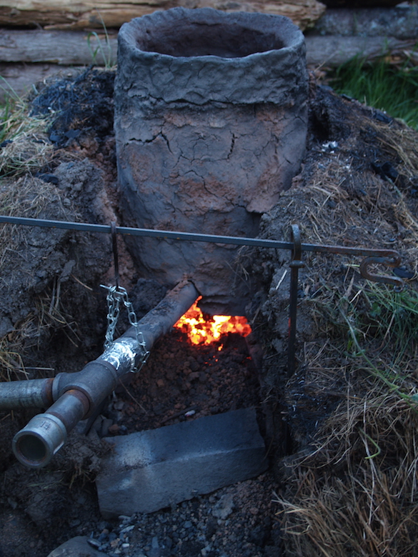
Figure 7 : Furnace just after extraction, June experiment.
Inside the furnace itself, there was
considerable erosion of the clay liner, following the expected
oval pattern centred around the tuyere. At some places (especially
close to and above the tuyere) the wall thickness had been reduced
from the starting 4.5 cm to as little as an estimated 1 cm thick,
all now heavily slag coated. The Icelandic clay mix did survive a
full smelting cycle, but with more erosion damage than was the
case with the EPK clay (higher firing temperature) normally used.
This depth of erosion suggested that if the wall thickness had
been much less than the 4.5 cm used, failure due to melting
through the walls would certainly have occurred. On examining the
overall damage to the furnace structure as it slowly cooled, it
was felt that it should prove fairly easy to replace the lower
sections that had broken away, and layer fresh clay onto the
eroded areas inside.
 |
 |
 |
 |
 |
 |
 |
 |
 |
 |
 |
 |
 |
 |
 |
 |
 |
 |
(additional) Photo mosaic of furnace after
Smelt A - bottom is marginally 'north'.
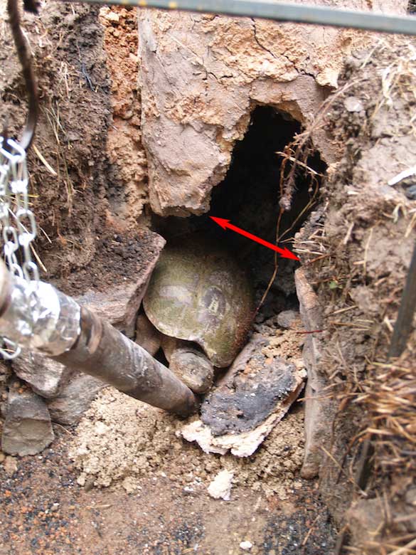
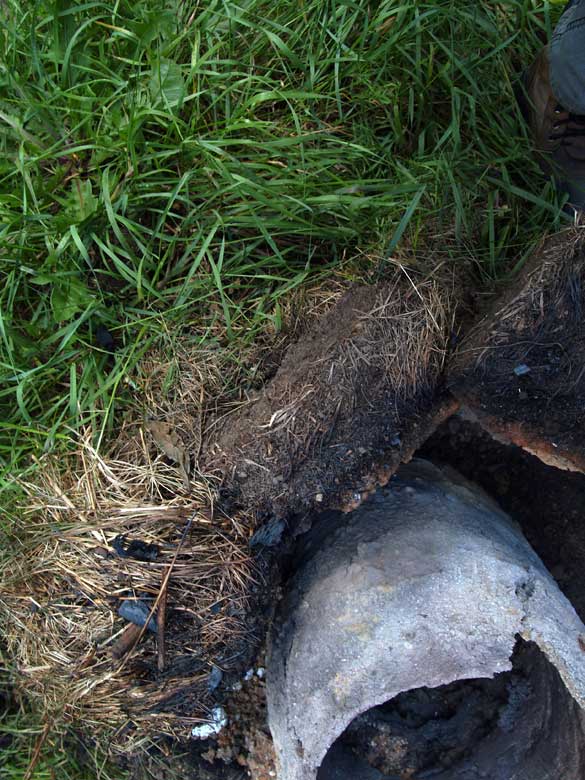
| In the early hours of the
morning following experiment A, a roughly 20 cm long snapping turtle had crawled into the still warm furnace! (12) The tuyere had been torn free, and a section of the front wall above this, roughly 30 cm tall by 15 cm wide, had been knocked out. (additional) Turtle as discovered the following mornng. In the image to the right, the red line shows the lower line of the furnace wall - after extraction. |
 |
The portions of slag bowl remaining after extraction were left in place. A metal cover was placed over the top opening of the furnace liner, but otherwise the sod structure was left exposed to natural weathering over the summer months, with the intent to schedule experiment B in early October. By August, however, with concern that the existing furnace might be suffering too much damage under late summer rains to be easily repaired for re-use, it was decided to move the scheduled second experiment forward. Repairs were undertaken the week of August 9 to 13. The remaining slag bowl was removed, with any lumps of slag still adhering to the inner walls broken free. The interior was cleaned down to the original starting hard base (dirt) level.
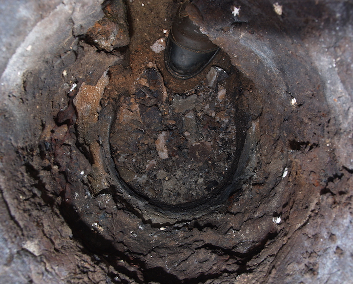
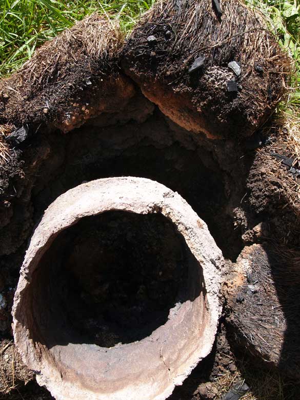
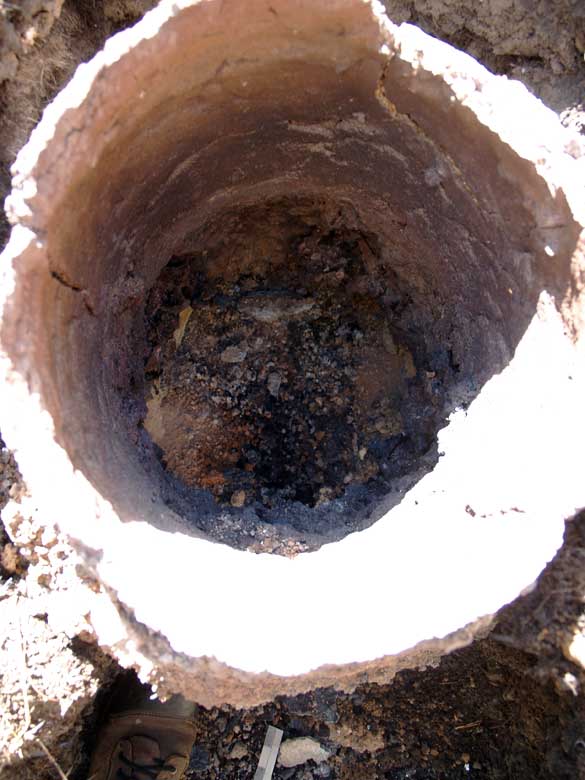
Figure 8 : View down the interior, after slag
clinging to walls and remaining lower bowl was removed.
Extraction arch to the top of this image.
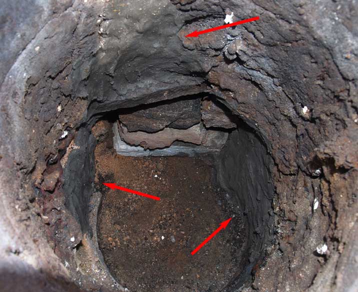
Figure 9 : Interior after patching, larger areas indicated. At the top is seen the straight line of the lintel stone, which will support the tuyere tip when that is installed. The edges of the extraction arch stones are seen below the lintel.
Overall the supporting grass sods
had slumped considerably, so an additional layer of sod was added
to the top, building up to roughly the same height as the
remaining clay liner. The last part of the repair process was
installing the same copper tuyere, positioned and supported much
as it had been for experiment A.
Smelt B – September 4, 2021
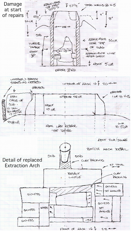
Figure 10 : Front elevation details of repaired furnace, ready for experiment B.
With re-use of Furnace A, most of the layout details remained the same, with these changes :Grass Sod Exterior : 6 layers stacked, height at 65 cm
Extraction Arch : stone filled, at 25 cm wide by 18 cm tall
Tapping Port : none, through gaps in stones
Stack Height (above tuyere) : 43 cm
Base Depth : 30 cm above hard base, charcoal fines layer adjusts depth below tuyere to 16 cm
Neil Peterson was the smelt master, with Dave Cox as lead hand, Rey Cogswell undertaking the extraction, Marcus Burnham as primary assistant (Darrell Markewitz supervising).
Air Volume : varies, (see ‘Air Rates’)
Total Slag Added : 4.3 kg
Total Ore Added : 26 kg
Total Charcoal Consumed : 65 kg (‘bucket’ = 1.97 kg / change from absorbed moisture)
Primary Sequence (over ore additions) : 156 minutes
Primary Charcoal Burn Rate : (average) 5.7 minutes / kg
Ore Rate : (average) 6.0 minutes / kg
Again in Smelt B, potential air volumes were
reduced towards what was considered possible via human powered
bellows systems. Again the first impact of this was to cause the
initial slag bowl to form too high, raising the level of liquid
slag upwards to where there the air blast was being effected quite
early in the process. This was partially corrected by using a
steel rod (9.5 mm diameter) to probe vertically, about 1/3 of the
furnace diameter back from the tuyere tip. This probe was forced
down through the still fragile bottom of the slag bowl, allowing
hot liquid slag to drain down into the charcoal fines layer, a
process repeated three times early in the smelt. Significantly, a
burning through of the front furnace wall, about 10 cm above the
tuyere, was observed at roughly 90 minutes into the primary
smelting cycle. This suggested that the lower volume air blast was
not fully penetrating into the furnace, but instead washing back
against the furnace wall at this location. Failure at the joint
between the new added clay and the original wall was also likely.
Roughly after the addition of the first two ore
charges, part of the extraction arch was opened, in this case by
the removal of one of the lower stone filling pieces. As in smelt
A, some of the lower charcoal fines were scraped out, allowing any
self tapping slag to flow below and soften the slag bowl, a
process that would proceed without any further intervention for
the remainder of the smelt.
The air rate was set slightly higher than for
Smelt A, certainly indicated by the shorter time per kilo
recorded.
Rey Cogswell undertook the full extraction
effort, the first time attempting this task. Lack of experience
would result in the extraction to be considerably drawn out, all
the while the furnace slowly cooling. The net effect was that the
bloom did not easily pull free of the encompassing slag bowl, and
a much larger mass than normal had to be pulled from the furnace.
The raw size of this mass would result in considerably more damage
to the lower front of the furnace than was expected. The stones
supporting the front of the furnace where all torn free. As the
strips of sod above the fallen lintel block collapsed, it was
obvious there had been a major burn through of the front wall,
with fused dirt now attached in a thick band in the area above the
tuyere. The entire tuyere and air supply system would pull off,
dropping into the fan of hot debris at the front of the furnace.
Between the extra mass now attached to the
upper wall, the removal of the supporting stones, and the force of
removing the large bloom encased in additional slag, the entire
clay furnace liner would slump outwards as one unit, pulling
partially clear of the rear sod structure.
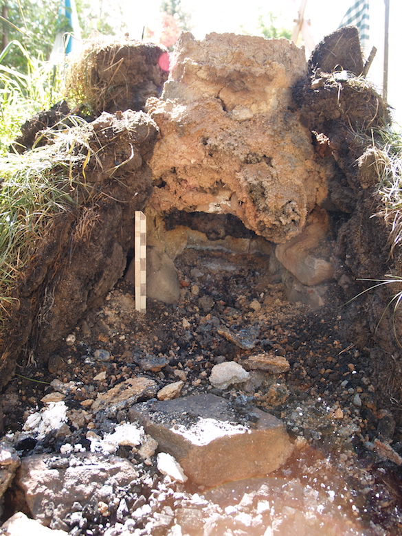
Figure 11 : Debris at the front of the furnace, after extraction. Note the mass of fused dirt, the result of the burn through of the front wall above the tuyere.The large stone in the foreground was the lintel block.
Final Bloom Weight : 8.2 kg
Yield : 32%
Although the total mass extracted was larger,
after one cycle of hammering to strike away clinging slag and
partial compaction, the bloom was roughly the same size as that
from experiment A. Once again it had a noticeably less dense
‘spongy’ texture and visibly retained considerable slag. Again the
yield recorded against ore volume is disproportionately high, with
excessive losses expected at the later bloom into bar compaction
phase.
One addition to the initial compaction work
here was the first inclusion of a large wooden ‘troll hammer’, as
observed in use by many European teams. This proved quite
effective for the initial phases of hammering off the clinging
slag ‘mother’ from the bloom itself.
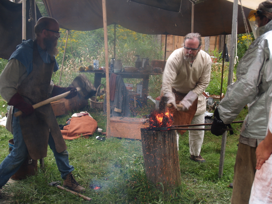
Figure 12 : Marcus Burnham with the ‘Troll
Hammer’, Richard Schwitzer with a standard sledge, Dave
Cox holding. The slag shows as the darker material still encasing
the hot metallic bloom core, more obvious in a photograph than in
real life.
 |
 |
 |
 |
 |
 |
 |
 |
 |
 |
(additional) Photo mosaic of furnace after
Smelt B - bottom is marginally 'north'.
 |
 |
| Showing clay liner slumped
towards tuyere side. Note gap between rear sod layers. |
Image down interior, tuyere
side to bottom. Note how interior slag bowl completely missing. |
Air Rates
A major addition to instrumentation had been made, and employed for this smelt. This was the purchase of an Omega HHF1000 flow meter. (13) This unit allowed for far more accurate measurements of the actual air volumes being injected into the furnace, over the roughly calibrated ‘sliding blast gate’ numbers recorded in the past. (14) One of the problems with the earlier measurements was that these were the potential total air available from the air equipment, and so did not account for the restrictive effect of the materials inside the furnace stack, certain to vary considerably over time. As this was the first use of this gauge, only infrequent measurements were made :
| Time | Event | Plate | Meter | Calculated |
| 10:11 | fill rough charcoal | 700 | ||
| 10:15 | air increase | 900 | ||
| 11:19 | full graded charcoal | 11.5 | 865 | |
| 11:23 | air reduced | 700 | not recorded | 550 |
| 12:00 | air increased | 800 | 8.8 | 660 |
| 12:44 | air increased | 900 | 9.6 | 720 |
The overall implication of these measurements is that earlier reported air volumes are only significant as they are compared to each other, not an accurate indication of exact volumes. Roughly, these earlier numbers are likely to be 20 % higher than the actual air amounts into the furnace. In working practice however, the physical burn rate (time for consumption of a given amount of charcoal) is used to determine the best functional air volume at any given point.
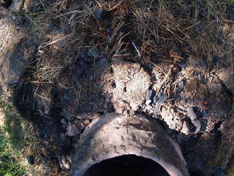
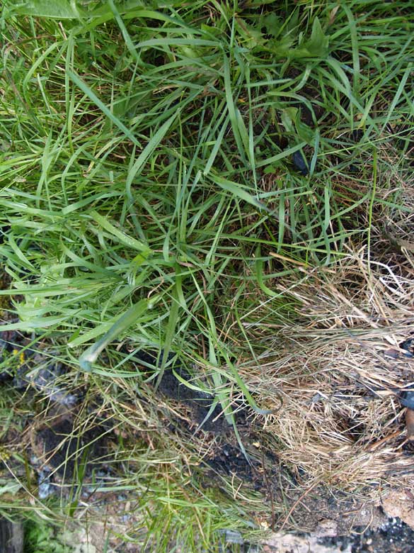
Weathering
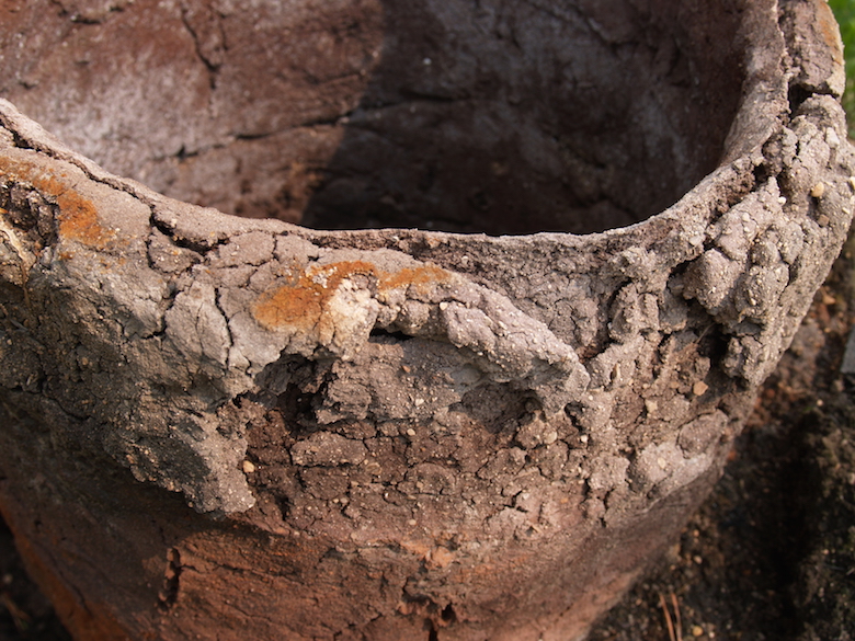
Figure 13 : Top edge of the furnace liner, above the tuyere – condition after 5 weeks from June firing.
The temperature gradient that is produced by
the firing of a smelting furnace has been seen to effect clay
composition walls in differing ways, which in turn results in
variations in damage effects as a furnace is exposed to weather
over time. There had been an unusual amount of rain over early
Summer at Wareham (a period where normally there had been little,
if any, rain in past years). The fracture line seen in figure 12
(image taken July 17) marks the division of heat effects between
the sintered interior and the ‘baked mud’ exterior, along the top
edge of the clay liner. By early August, the outer portions had
broken free along this line. There had also been considerable
overall slumping of the sod structure, again due to the exposure
to rain.
The plan for Smelt C was to leave the furnace
standing, with a roughly 100 cm diameter round wooden cover
(‘shield sized’) placed over the top. Normally there is a smelt
experiment in later June, so this schedule would subject the
furnace to a full Ontario winter of freeze and thaw, then the
expected spring rains. (Freezing temperatures can be expected at
Wareham by later October, snow by mid November, eventually
accumulating to a metre or more in depth.)
It was clear however, even at the end of Smelt
B, that a significant rebuild of both the inner clay liner and the
surrounding sod structure would be required before any attempt to
use the existing furnace again. September in Central Ontario also
saw a huge increase in rainfall over past decades however, clearly
accelerating these effects. (15)
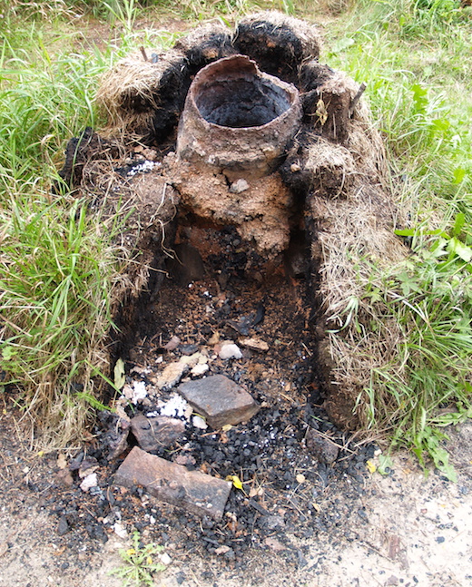
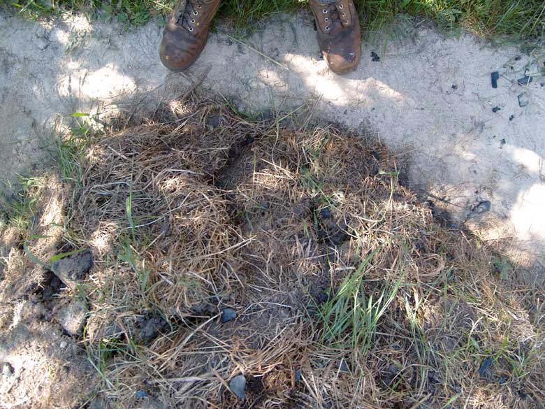
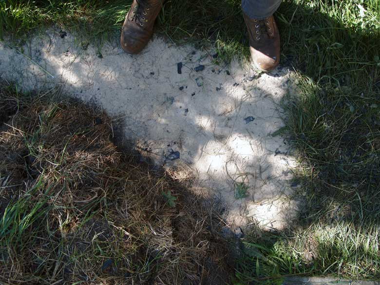
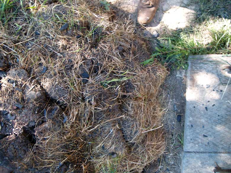
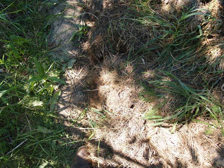
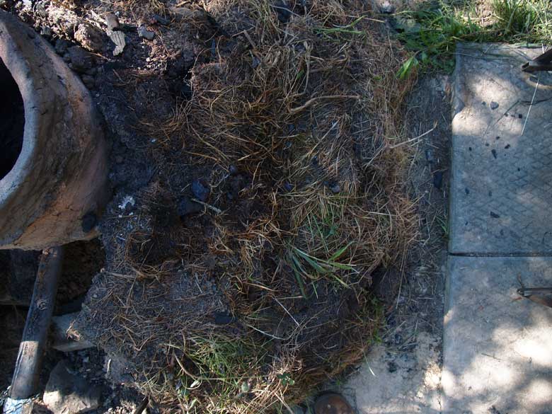
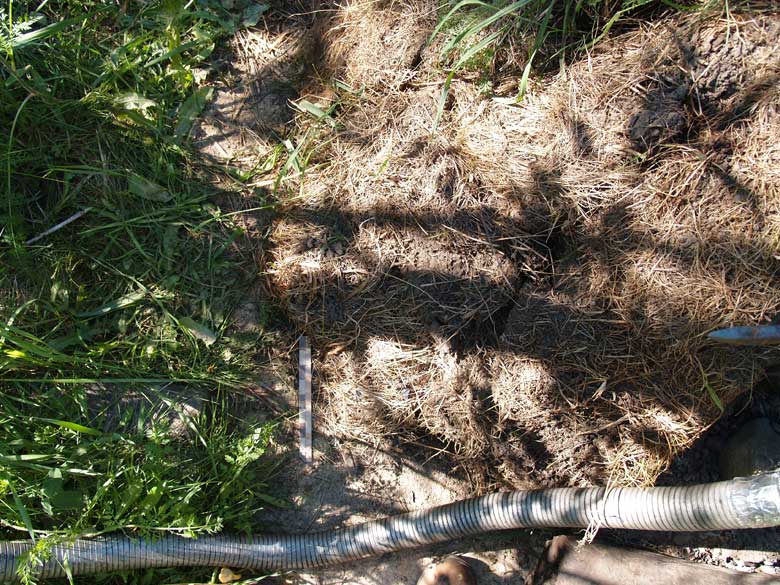
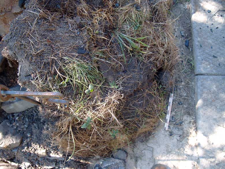
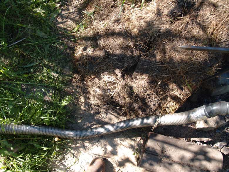
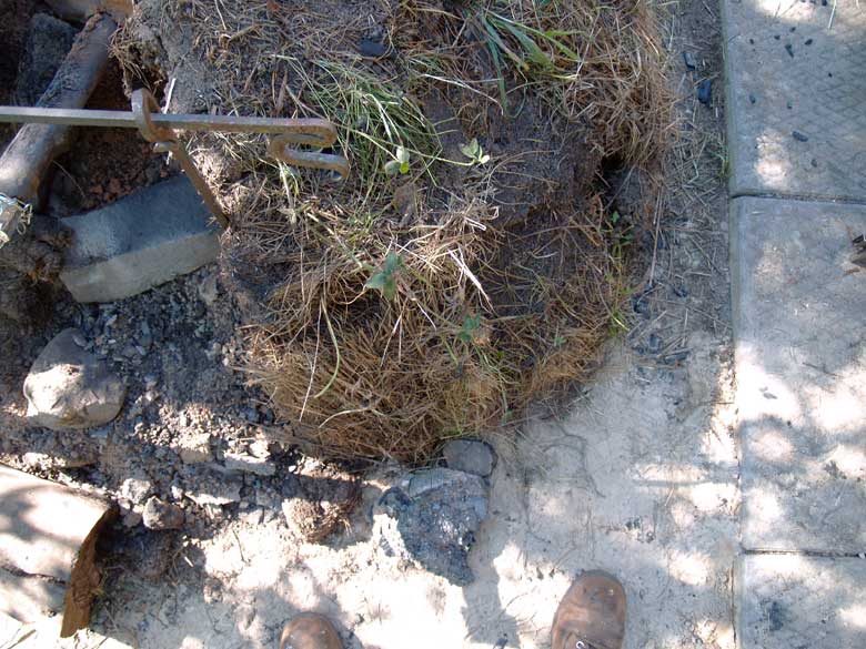
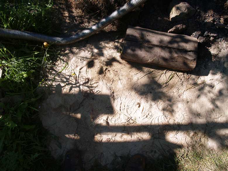
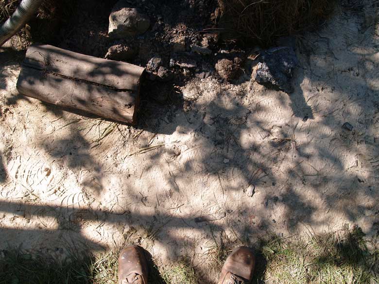
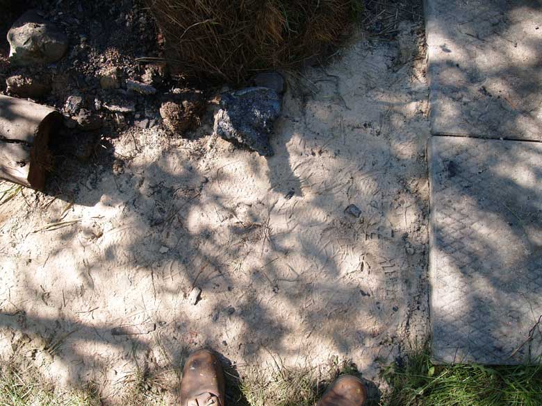
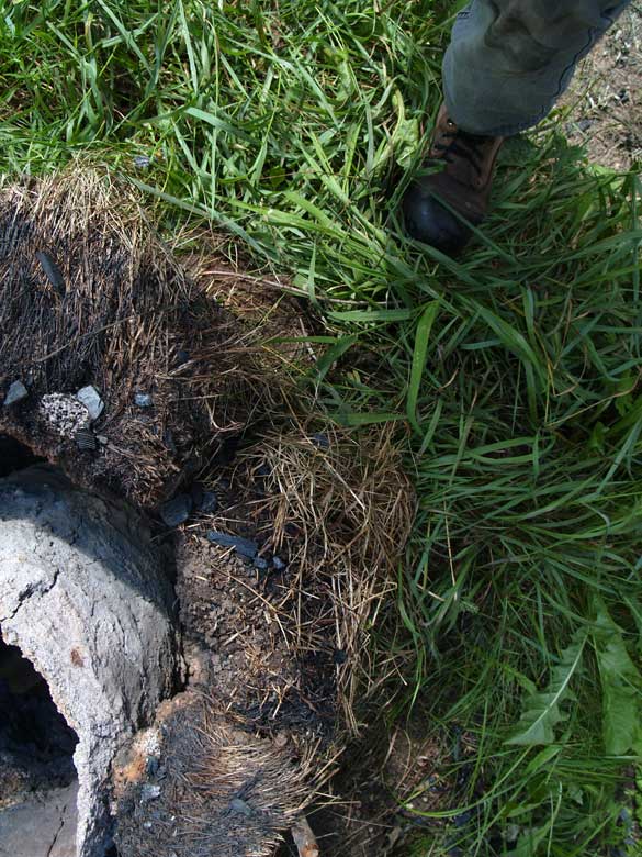
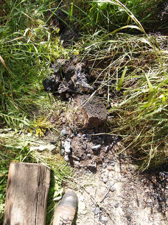
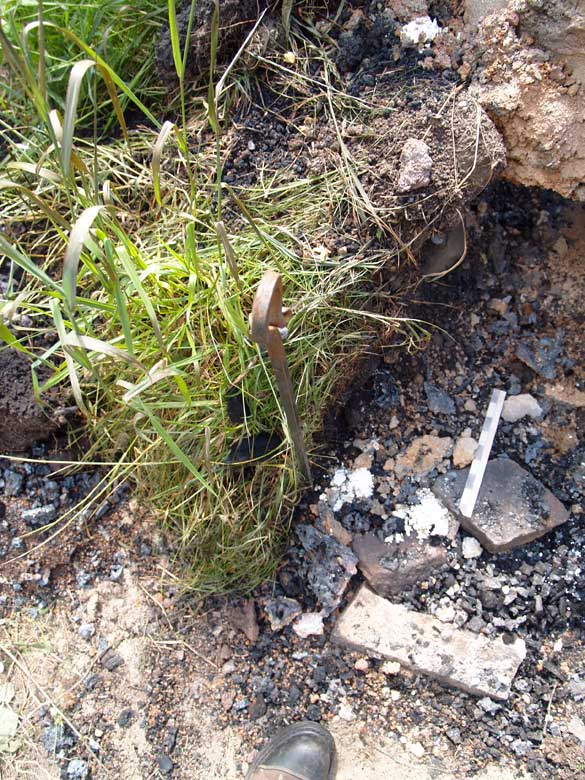
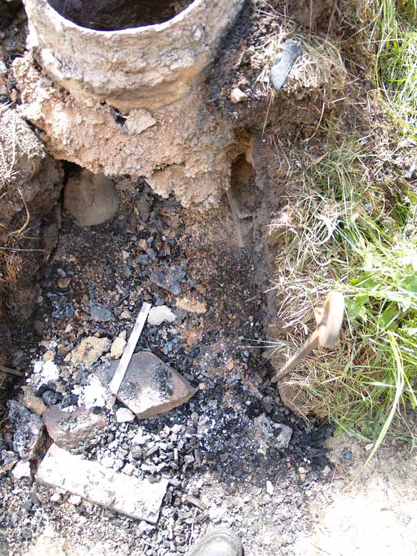
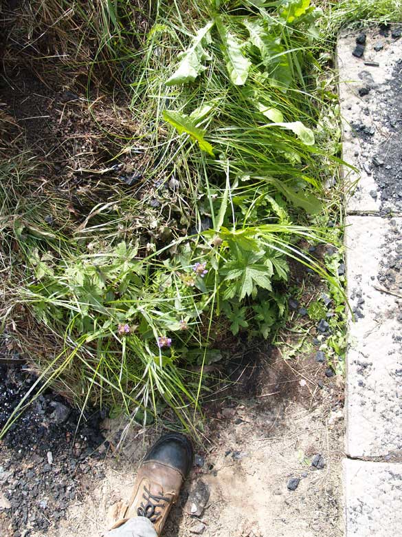
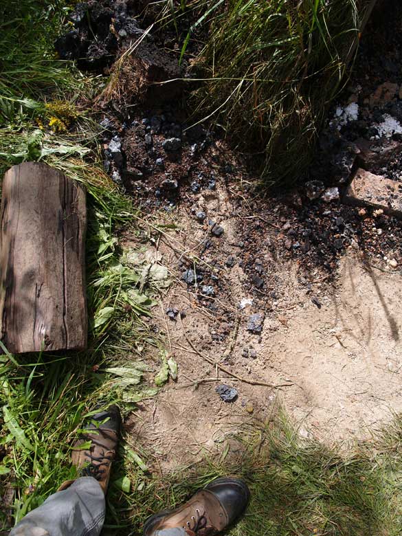
Figure 14 : Rain erosion, September 24 - compare with post smelt image seen above (figure 11).
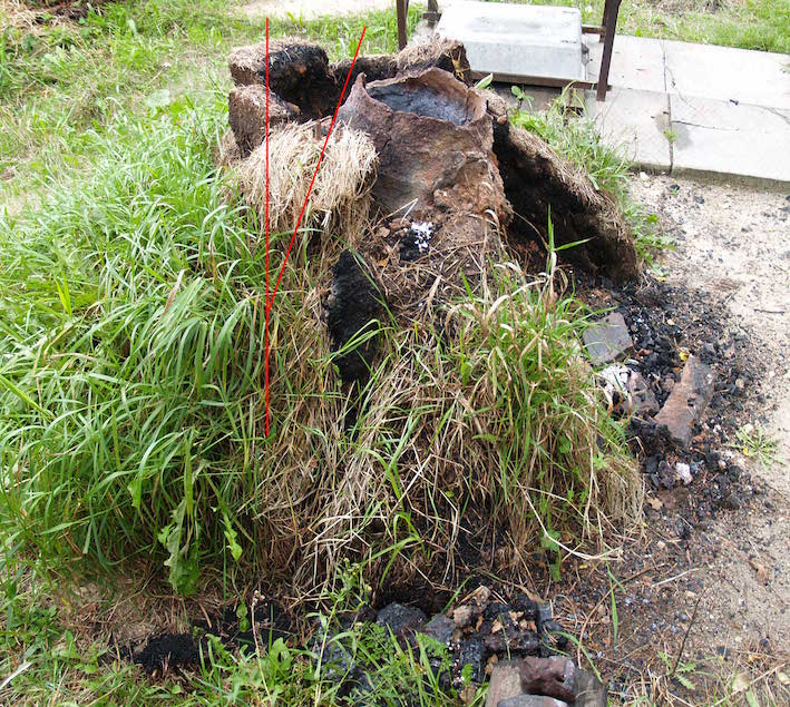
Figure 15: Side view, showing slumping of the
furnace towards the extraction side (red lines).
Slag moved from the working area (while hot) in the
foreground.
Figure 15 clearly shows the slumping forward
of the remaining clay liner, a total of roughly 17 degrees off the
original vertical, over the first 20 days since the last firing.
Any attempt to re-use this furnace would most certainly require as
a first step clearing away the falling dirt, and restoring the
line of the liner to vertical. Given the overall fragile condition
of the clay, especially along the mass of fused dirt on the front
wall, it is considered unlikely that such a re-adjustment would
even prove possible.
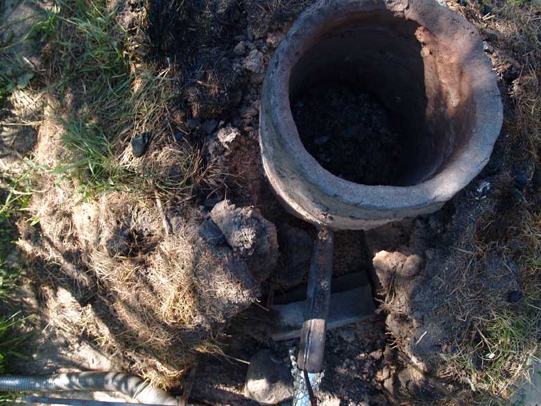
It was decided instead to leave the furnace
remains openly exposed to weather, basically the start of
observing the effects of environmental processes on this specific
furnace type. It is the long term plan to continue recording the
effects of natural weathering on this furnace, the hope is over at
least a decade.
Time Study
In an effort to get some concept of the labour involved in building the furnace described, then operating this through a full smelting cycle, some attempt to keep time / labour records was made. The build work was undertaken by a single, well experienced individual, the time indicated is ‘person hours’. It should be noted that digging / cutting was all undertaken using modern steel bladed tools.
There was no record made of the time required for cutting and hauling sod strips.
A quantity of timber had been gathered and prepared, as ‘log’ pieces cut to roughly 2 meters and averaging 10 cm diameter. This material came from local roadside clearing, so the effort of cutting was not considered. No detail of the time required for gathering was recorded, and this material was not used.
Although time for digging the earth fill was recorded, this remains highly dependant on the difficult conditions at Wareham (soil typically at least 1/3 rock and stone), balanced by the significant difference between modern and Viking Age digging tools. Again this material was not used.
As the base clay body was purchased, no time is included here. This could be considered to contribute considerable labour if local raw clay was used, with the distance to source also significant. (About one hour to measure and mix components)
Hand shredding the volume of dry horse manure took one hour. Gathering time was minimal (so not included).
Hand mixing and preparing two batches of the clay mixture took two hours.
Including setting the earth pad, building up the clay liner, setting the stone supports, then applying the sod layers, furnace build was about 9 hours.
Once the furnace was completed, it was left several days to allow the clay to dry to ‘leather hard’.
The initial drying fire required about four hours. As this required simply adding a handful of dry wood splints every 5 – 10 minutes over this period, other preparation work was undertaken at the same time. This included preparing the work site and hauling charcoal, setting the tuyere and air system.
Mixing and preparing to sun dry ore analog took one hour.
This puts the total build time for this
furnace at 17 ‘person hours’. Importantly, this is not
including gathering required materials.
One significant labour factor that is missing
is the time and effort related to making charcoal. Commercial
charcoal was used, purchased as ten, 8 kg bags per smelt.
Another major labour component not included
here is that required to find, gather, and potentially roast, a
suitable quantity of natural bog iron ore. The DD1 analog used for
these smelts requires infrequent moving over the drying period
(several days, dependant on weather).
| (minutes) | Team Size | Pre-Heat | to Temperature | Main Sequence | Burn Down | Extraction | Event Total |
| Smelt A | 3 | 127 | 28 | 393 | 58 | 20 | 626 |
| Smelt B | 3 | 82 | 86 | 156 | 40 | 30 | 394 |
| Average | 105 | 57 | 275 | 49 | 25 | 510 | |
| TEAM | 314 | 171 | 824 | 147 | 75 | ||
| LABOUR | minutes | 1530 | |||||
| as hours | 25.5 |
team leader (smelt master) - slag management, air follow control, overall operations
lead hand – ore and charcoal additions, assistance as required
record keeper – maintaining addition and event notes, weighing ore amounts
During the initial pre-heat phase, charcoal
is also broken and screened for size.This usually occupies two
individuals for roughly one hour (at the volumes used here). Tap
slag and ore (depending on type), are also broken to size. During
the extraction phase, one individual frees the bloom, with one
closely assisting, and the third maintaining the furnace and
safety. Compaction normally involves one person holding the mass,
two striking. It should be noted that different individuals may
take on these various tasks over the course of the long hours
required.
The smelt sequence records made do not include
the full time required for the burn down, or the exact time
required for extraction or the initial consolidation process. Most
commonly, work on a typical iron smelt day starts at 8 am for the
team leader, with final walking off the work site at roughly 6 pm
(for a smelt of this size).
There is always work setting up tools and
general preparations at the start of a smelt, then an initial
clean up of the work site afterwards. Roughly these combine as one
person over 2 hours total. (and are not included below)
That all being stated, the average labour
given for the actual smelt at 25.5 person hours is at least
a reasonable estimate. It is important to remember that this
represents a total using the faster burn rates possible via an
electric blower. As well taking longer for the entire sequence,
there is also a major labour component to the continual operation
of a human powered bellows system of suitable volume / size. Past
experience of this team suggests an addition of three individuals,
working in short rotation over an expected 8 to 10 hours.
Within the limitations given, this paces total
labour for one smelt at roughly 44 + person hours for the
creation of a roughly compacted 8 kg bloom (not counting
bellows workers). It should be remembered that this is still not
to the desired end product, fully compressed ‘currency bars’.
Conclusions
Initial heating tests of samples of the
simulated Icelandic clay had suggested that there might be some
problems with melting of this material when subjected to the
normal firing temperatures inside a bloomery iron smelting
furnace, expected to be as high as 1250 + C.
The decision to build the clay walls to a
thickness of 4.5 cm was primarily based on experience gained
earlier during the Phase 2 experiments. This turned out to be a
functional minimum, at least as demonstrated by Smelt A. Through
that fairly standard firing sequence, the normal erosion effects
that are concentrated around the tuyere had reduced the wall
thickness to as little as 1 cm in some spots.
Another expected result of the lower melting
point exhibited by this clay body was an increase in slag produced
(over the amounts expected from the ore analog). This proved to be
the black (iron rich) and importantly, fluid type. This did
require both tapping out and other management processes over the
course of both smelts to ensure the air blast through the tuyere
was not interrupted.
Used as component of a well understood furnace
layout and employing a standard firing process, the simulated
Icelandic clay proved quite suitable through a single firing.
Primary Test B : How does this furnace perform with repairs and a second firing?
It was clear however, that excessive internal
erosion had resulted during the first firing. After breaking clear
the first slag bowl that remained, generally it proved fairly easy
to apply new clay on to the inner surfaces, in an attempt to
restore the original 4 – 4.5 cm wall thickness.
The effectiveness of needed repairs was further
complicated by two factors (both beyond the control of the
experiment). The first of these was the additional damage done to
the middle front wall by the turtle. The second was a two week
delay and wet weather, between the undertaking of repairs, and the
mounting of Smelt B. (15) Both these factors may have contributed
to less than ideal bonding between the existing wall and the
repairs applied. This most likely the reason for the burn through
failure experienced in Smelt B.
It did prove easily possible to repair a
previously used furnace and effectively undertake a second full
smelt.
Primary Test C : How does a well designed furnace, on the Háls pattern, endure over time?
The effects of the additional turtle damage,
plus that caused by less experienced hands during extraction in
Smelt B, certainly accelerated overall impacts to both the clay
liner and the surrounding sod structure.
The original outline for Phase 3 called for the
furnace to be somewhat covered, and otherwise exposed over an
Ontario winter. In light of the damage at the end of Smelt B,
coupled with the effects of unusual rainfall over the month of
September, it has been decided not to attempt to re-use this
furnace. The impact of overwintering and a third firing thus
remains untested.
Instead, the furnace and surrounding work area
will remain in place and be exposed to the natural cycle of
weather over an extended period into the future – ideally many
years. As it degrades, it is hoped that records of that process
may serve to have some value to archaeologists when interpreting
ancient smelting furnaces.
One additional observation from the two smelt experiments of Phase Three lays in the ore into iron results. Both smelts used identical ore analog, ore amounts and charcoal type. Air volumes applied were roughly similar. The overall working sequence both times was also similar, outside the fine detail of needed slag control. The end results where found to be roughly identical as well, with unusually high bloom sizes and yield numbers, with the blooms created of similar quality.
This all proves the basic viability of this reconstruction of the Háls working system, at least for a limited set of firing cycles. The placement of several furnaces in close proximity at Háls suggests that these also were short use cycle structures, tore clear and re-made as each failed.
Future Experiments?
At this point in this extensive experimental series, it is felt most of the major elements of furnace design have been tested through full smelting sequences. Obviously, the major overall discrepancy remains the difference between the materials available at the Ontario location, and those at Háls in Iceland. The most obvious solution would be to undertake at least a limited experimental series in Iceland, but simple logistics (primarily funding) make this unlikely. There are three elements understood as being important :
Gathering locally available primary bog iron ore. This is mainly expected to result in differences in slag volumes generated, which in turn will provide insight into what methods of slag control are required. There will also be a significant relationship to potential yields, which in turn effects consideration of total iron production at Háls. (Even with use of local ore, this material may still differ in fine detail from archaeological samples, simply because of environmental changes over the last 1000 years.)
Gathering locally available clay. Again this will effect slag production and interior erosion, suggesting the use life of individual furnaces. (This still may represent an unknown, as it is uncertain if the source found by Hayeur-Smith was the one utilized at Háls.)
Building with Icelandic turf. This may actually have minimal impact on the furnace’s operation, where a full clay liner is used. It may prove significant in assessing the impact of weathering over time however.
As detailed, the exact type of tuyere used at Háls, and its method of mounting, remains unknown. The larger series has tested both ceramic and copper tuyeres, using primarily inserted mounts, but also variations of the ‘blow hole’ method. Two further tuyere types remain untested by this team :
Heavy forged (bloomery) iron as insert tuyeres. (Modern steel pipe is commonly used by many experimenters, including early work by this team, but is not considered a true substitute.)
Use of either bone or antler tubes, for the blow hole method, either mounted flush to the furnace exterior, or separated by a gap. (Even if these materials proved resistant enough to the radiated heat, the general problems produced with the blow hole method would remain.)
The impact of modern electric blowers versus human bellows systems for supplying air still remains to be tested in detail. The exact form of bellows used by Viking Age Icelanders in the iron smelting process remains unknown, as there is no direct artifact evidence for smelting equipment that has been found. There is no doubt various human operated bellows systems, applied to this type of ‘short shaft’ bloomery furnace, will result in the production of metallic iron, as many teams of iron makers (including this group) have certainly proven. Most of these efforts are experiential however, reporting (when done at all) has been more qualitative than quantitative. Research into air systems remains ongoing.
Acknowledgements
The author would like to acknowledge the huge amount of enthusiastic, volunteer, labour contributed now for over two decades by members of the Dark Ages Re-Creation Company. In addition to the primary workers credited for their larger roles over these two experiments, the following also directly participated :
Richard Schwitzer
Marcus Burnham
Kay Burnham
Kelly Probyn-Smith
Considerable thanks goes to Kevin Smith, who has become a close advisor over 20 years of learning and investigation to the Norse of the North Atlantic. It is largely due to his encouragement and constant assistance that all this work into bloomery iron smelting had shifted from the experiential to the truly experimental.
A special thanks to the additional financial contributions of Neil Peterson, who donated all the charcoal used in the 2021 experiments.
Notes
1) During the 2000 excavations, a two by two metre square was excavated down to the top surface of the furnace slag bowls, and exposing only part of what may be a larger iron making area. (Smith, 2005) Unfortunately, Smith's work on the site was halted at this point.
2) The size of this bank was given as ‘roughly the size of a tractor trailer truck’. Information provided over a long duration series of private e-mail communications between Kevin Smith, Michelle Hayeur-Smith, Neil Peterson, and the author.
3) A detailed report is available : Markewitz, D., 2021. Sticking To It – a clay mix for Icelandic. https://warehamforgeblog.blogspot.com/2021/06/sticking-to-it-clay-mix-for-icelandic.html [last accessed November 2021]
4) One outstanding concern is how similar in structure the cut
grass sod at Wareham in Central Ontario is to the natural Viking
Age turf at Háls. The environment in Iceland is radically
different, as is the vegetation, even the composition of soil
itself. In the Phase 2 tests, there was found to be an obvious
difference between grass sods cut at Wareham, and those cut for
experiment 8, about 45 km south at Laurel. A fuller discussion of
this difference in materials is included in : Smith, P. K.,
Markewitz, D., and Peterson, N.. Now with 70% Less Clay!
Experiments with Viking Age Icelandic Turf Walled Iron Smelting
Furnaces. (publication pending).
A short video overview was presented at the EAC 12 virtual
conference, March 2021. https://youtu.be/7Ltz5NG2BP0
[last accessed October 2021]
5) See a fuller discussion of building methods and their indications : Markewitz, D., 2021. Stacking Up – on constructing clay furnace walls. http://www.warehamforge.ca/ironsmelting/stacks/stacks.html [last accessed November 2021]
6) This method (internal wicker form) was used for the first test in the ‘Pictish’ series. See the overview: Markewitz, D., 2014. Late Pictish Late Iron Age Smelt. https://warehamforgeblog.blogspot.com/2014/06/pictish-late-iron-age-smelt-overview.html [last accessed November 2021]
7) It is unknown what, if any, silica (as sand) might have been present in the natural bog iron ore available and used at Háls, and there is limited evidence of tapped slag. It was fully expected that slag tapping would be required in these experiments, based on past use of the DD1 ore analog. It is thus possible that the entire dynamics of slag control, as used here, including the implications to furnace design, may not resemble that used by the Icelanders.
8) Once exception to this are distinctive slag rings, which are formed around the end of the copper tuyere that is exposed inside the furnace. Such ‘end caps’ are quite fragile, but if recovered, can indicate tuyere penetration past the inner wall, insertion angle, inner and outer diameters (thus tube wall thickness). Similar slag rings were excavated at Jamestown Settlement, Virginia, examined by the author in 2012. See : Markewitz, D., 2012. Slag Tuyere Rings. https://warehamforgeblog.blogspot.com/2012/04/slag-tuyere-rings.html [last accessed November 2021]
9) The blower used is a high volume ‘compression’ type, with a specified maximum volume at 1400 litres per minute. Actual delivery is controlled by a sliding plate across the output. This has been (very!) roughly calibrated to 100 litre hash marks. The whole question of how well any electric blower system can simulate the air produced from probable Viking Age bellows types is considered an entirely separate area of investigation. Although a number of potential Norse style bellows have been tested in past experiments, these all require a considerable number of additional workers, beyond the smelt team itself, to operate effectively. See Markewitz, D., 2012. An Iron Smelt in Vinland. http://www.warehamforge.ca/ironsmelting/LAM/Smelting-Vinland-V3.pdf [last accessed November 2021]
10) This is only a brief description of the standard working sequence that has been developed over two decades by this team. A fuller description of the process can be found : Markewitz, D., 2012. “If you don’t get any iron ...” - Towards an Effective Method for Small Iron Smelting Furnaces. EXARC Journal, Issue 2012-1. https://exarc.net/issue-2012-1/ea/if-you-dont-get-any-iron-towards-effective-method-small-iron-smelting-furnaces [last accessed November 2021]
11) It needs to be remembered that the desired end product for ancient iron makers were fully compressed working bars – not semi-product blooms. Modern makers too often report their ore to bloom yields, without reference to starting iron content of ore, or any consideration of bloom density.
12) The snapping turtle (Chelydra serpentina) is native to North America. The smelting area at Wareham is adjacent to a small pond, and a creek runs behind the (rural) property . See : https://en.wikipedia.org/wiki/Common_snapping_turtle [last accessed August 2021]
13) One of the problems effecting all Independent Researchers is limited access to high quality (and priced!) instrumentation. For details of this instrument, see : https://www.omega.com/en-us/test-inspection/handheld-meters/anemometers/p/HHF1000-Series [last accessed August 2021]
14) See : Markewitz, D., 2021. Mind the Blast – Correcting Reported Air Volumes. https://warehamforgeblog.blogspot.com/2021/09/mind-blast.html
15) Records from Environment Canada give the past average rainfall for the area around Wareham for the month of September as 7.7 cm total. In 2021, there was a single one day amount of 5.6 cm. Although exact overall total for September were not available at time of writing, September 2021 certainly had the highest amount of overall rainfall, often as heavy downpours, seen over 30 + years of personal observation.
16) The repair work was undertaken on August 18, with the second firing initially scheduled on the 20th. Due to unforeseen events, it was necessary to postpone Smelt B, and the shift of roles during that experiment.
Works Cited :
Geology Science, 2018, Basalt. https://geologyscience.com/rocks/basalt/ [last accessed December 2021]
Geology Science, 2018, Granite. https://geologyscience.com/rocks/granite/ [last accessed December 2021]
Markewitz, D., from 2006 (ongoing). Experimental Iron Smelting. http://www.warehamforge.ca/ironsmelting/index.html [last accessed December 2021].
Markewitz, D., 2008. Working towards an Icelandic Viking Age Smelt Based on the remains at Háls. http://www.warehamforge.ca/ironsmelting/Hals/index.html [last accessed October 2021]
Markewitz, D., 2014. An Iron Smelt in Vinland – Converting
Archeological Evidence to Practical Method. in Can These
Bones Come to Life? : Insights from Reconstruction, Reenactment,
and Re-creation - Volume 2. Cramer, M. (editor), Feelance,
Wheaton, Illinois.
The full text of the initial version (V3 - June 2010) : http://www.warehamforge.ca/ironsmelting/LAM/Smelting-Vinland-V3.pdf
[last accessed November 2021]
Markewitz, D., 2021A. ‘Evidence of Absence’ - The Erosion of Bloomery Iron Furnace. http://www.warehamforge.ca/ironsmelting/erosion/erosion2021.html [last accessed October 2021]
Markewitz, D., 2021B, Standardized Reporting of Experimental Iron Smelting – a modest proposal, the EXARC Journal, 2021-1 (also available as pdf) http://www.warehamforge.ca/ironsmelting/standard/SmeltingMeasures.html [last accessed January 2021]
Pleiner, R., 2000. Iron In Archaeology – The European Bloomery Smelters. Archeologicky Ustav Cr, Prague.
Sauder, L., 2020 (?- nd.). Forging and using a Wrought Iron Tuyere. https://s3.amazonaws.com/images.icompendium.com/sites/eliz2406/sup/3696376-Wrought-Iron-Tuyere-report.pdf [last accessed November 2021]
Smith, K.P., 2005. Ore, Fire, Hammer, Sickle: Iron Production in Viking Age and Early Medieval Iceland, in AVISTA Studies in the History of Medieval Technology, Science, and Art, Volume 4. Bork., R (editor). Ashgate, Aldershot, UK.
Also available as PDF : https://www.academia.edu/191535/Ore_Fire_Hammer_Sickle_Iron_Production_in_Viking_Age_and_Early_Medieval_Iceland [last accessed October 2021]
Additional References
The detailed sequence data for these two experimental smelts are available online :
Smelt A, June 20, 2021 :
http://www.warehamforge.ca/ironsmelting/iron2021/June21/june-21-data.htm
Smelt B, September 4, 2021 :
http://www.warehamforge.ca/ironsmelting/iron2021/September21/data-9-21.htm
[both last accessed November 2021]
Markewitz, D., 2021. Into Phase Three – Continuing Experiments with Iron Smelting, based on Háls, Iceland. http://www.warehamforge.ca/ironsmelting/phase3/phase3.html [last accessed November 2021]
Peterson, N. 2006 to present. Experiments in the creation of iron using Viking-Era Norse techniques. http://www.darkcompany.ca/iron/index.php [last accessed December 2021]
About the Author...
Darrell Markewitz from Ontario, Canada, has been a professional artisan blacksmith since the later 1980’s. Known as a specialist in the Viking Age, he has contributed to a number of major museum exhibits, including extensive work for Parks Canada at L’Anse aux Meadows NHSC. His interest in bloomery iron smelting started there in 2001, and his extensive practical and experimental research has included participation in a number of international projects and academic conferences over the last two decades. As well as a number of published academic papers and journal articles, his past work is well documented on an extensive web site : www.warehamforge.ca/ironsmelting , plus commentaries on his blog : warehamforgeblog.blogspot.com
Darrell Markewitz
the Wareham Forge
307377 Centre Line A
Proton Station, Ontario
CANADA – N0C 1L0
info@warehamforge.ca
www.warehamforge.ca
Unless otherwise indicated :
All text and photographs © Darrell Markewitz,
the Wareham Forge.