Experiments with Viking Age Icelandic
turf walled iron smelting furnaces
:
2007 - 2016
Darrell Markewitz : Independent Researcher, Ontario - Canada
Neil Peterson : Independent Researcher, Ontario - Canada
Abstract
Iceland's Viking Age settlers came from regions with long traditions of bloomery iron smelting. They faced a significant problem, however, as the clay typically used in Iron Age furnace construction was either unsuitable, or extremely limited, in Iceland. Excavation of a major 9th-10th century iron production site at Háls by Kevin P. Smith illustrated an alternative – walls made of conical stacked grass turf, with or without a thin clay lining.
From 2007 to 2016, a group of independent researchers in Ontario, Canada, executed a series of eight experimental bloomery iron smelts to investigate possible furnace designs and working methods based on this archaeological evidence. This series related to a second, concurrent, project investigating iron smelting at Vínland (L’Anse aux Meadows NHSC), and more recent furnace builds suggested by excavations at Skógar, Iceland.
This
paper will describe how the archaeology at Háls was interpreted
into a possible working system, provide an overview of how
individual elements were tested and combined for successful iron production, and
suggest directions for future investigations. Further, this
report helps to illustrate how valuable insights can be provided
through direct experience, even with limited resources for
experimentation.
Author’s Note :
A Powerpoint to video presentation, outlining the full paper under preparation, was delivered at the EAC 12 virtual conference, March 2021. (https://youtu.be/7Ltz5NG2BP0). This is a modified version of the more complete formal paper, primarily in that it omits a detailed overview of the archaeology of Háls, and how it fits into the larger consideration of iron production in Viking Age Iceland, to be contributed later by Kevin P. Smith. Presented here is a 'web integrated' text, describing in considerable detail the individual experiments, and including a larger series of images than are likely to be seen in the future published paper.
Working an Experimental Series
Setting the Stage
The first explorations into Viking Age iron smelting methods in Canada started with a week-long workshop session at L’Anse aux Meadows NHSC for Parks Canada in 2001. Participants were Dr. Birgitta Wallace, who had worked extensively at that site, Arne Espelund, an independent archaeo-metallurgist, local staff interpreter Mark Pilgrim, and Darrell Markewitz as a metalworker with a grounding in Norse material culture. The excavations at L’Anse aux Meadows had revealed evidence of what was the first known iron smelt in North America, by a group of Norse Greenlanders and Icelanders some time about 1000 AD (Stine Ingstad, 1977). The remains were quite limited, so any details of the actual physical methods employed were lacking. Although a single attempt to build and operate a (largely) theoretical bloomery furnace was made, the results could be most generously described as ‘everything you know is wrong’.
On a return to Ontario, Kevin Smith would take part in the second attempt, at Wareham in May of 2002. Again a failure to produce iron, but under Smith’s influence the beginnings of an experimental approach to the undertaking started.
An important consideration to all of the work described here (and the considerable volume of related work before, during and after) is that this research is undertaken by what would be most elegantly called ‘independent researchers’. Individual team members vary considerably in training and level of interest, with a few who do work in related fields at their ‘day jobs’. All of the experiments are privately funded, there is no institutional support for instrumentation or easy access to a research library. These factors influence the level of scientific rigour applied within both this, and various other, experimental series undertaken. (Markewitz, 2020)
Although the first attempts at iron smelting were firmly rooted in the archaeology at L’Anse aux Meadows, it was quickly realized that a more reasonable path to a historic method had to start with acquiring the basic skills of how to actually operate a direct process bloomery furnace. As luck would have it, several of the working group were able to attend a demonstration event by Lee Sauder and Skip Williams at the Frontier Culture Museum at Staunton, Virginia in early spring of 2003. Sauder and Williams had at this point developed a functional bloomery iron system, although most certainly one far removed from a Viking Age type. (Sauder, 2000) Over the next decade, Markewitz would become a founding member of the Early Iron Group here in North America, composed primarily of artisan blacksmiths, a number of which also worked at living history sites. Significant to an understanding of bloomery ironmaking would be the series of ‘Smeltfest’ workshops hosted by Sauder. Participants were broken into small teams, and identical furnaces would be built and operated to test individual design aspects. One clear result was the eventual development of what has become known as the ‘Norse Short Shaft’ slag tapping furnace build (Markewitz, 2012a). Over the course of 20 years and over 85 experimental and demonstration smelts (to date), not only has a good practical experience of the process been gained, but also a much better understanding of the principles of experimental archaeology has been learned and applied.
All this is important to place as background to the specific experimental series detailed here, based on the archaeology at Háls. Smith would not publish his descriptive paper on his excavations there until 2005 (Smith, 2005). As will be detailed, the first measured consideration of converting this evidence into a functional system started over summer of 2007.(Markewitz, 2008a) Despite having participated in 24 smelts to that point, the authors still did not feel they had a good working understanding and effective experience with bloomery iron production until the early part of 2008.
Elements from Háls
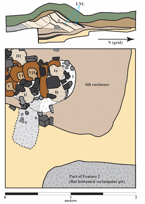
Figure 1 : Excavation Plan
at Háls
(Image © Kevin Smith, 2021)
The following
were the primary archaeological elements considered important for
re-creating a possible working system, based on the archaeological
evidence uncovered at Háls:
The working traditions underlying furnace design and working methods were most likely to be from Norway, the source point of the majority of early Icelanders themselves. Norwegian furnaces are primarily built with large stone slabs, or stones set into a clay matrix. (Espelund, 2013) Care must be taken with this generalization, as single use, individual farmstead furnaces are certain to differ from more robust builds found at ‘industrial’ / primary purposed iron making complexes.
The basic working system for making bloomery iron requires the following : (Markewitz, 2012a):
Obviously the volume of the furnace will be a significant factor in determining the amount of charcoal required to fill. An additional factor is the material used for the furnace walls, and the raw thickness of the construction. More massive furnaces require more energy to bring them up to functional temperatures. If measured by weight, charcoal species does not appear to be a factor (2) Again based on past experience, furnaces in the size range of those at Háls have been found to require in the range of 20 kg of charcoal to establish an effective reaction column at temperature. Over this base amount, experiments by many contemporary bloomery iron makers have shown consumption of charcoal typically approximates the weight of ore added. This puts the amount of charcoal required for the size of a smelt as suggested here into the range of at least 50 kg.
Generally there is a sliding scale relationship to the amount of ore used against the relative yields expected. A functional slag bowl needs to be established in the bottom of the furnace, either through the first additions of ore, or some other method. Once metallic iron starts collecting, increasing ore amount will increase bloom weight and effective yields. Again, experience has shown that a minimum of about 8 to 10 kg ore is required in furnaces of this diameter before any significant iron will accumulate. This working team generally undertakes smelts in the 30 kg ore weight range, and has come to expect bloom yields in the range of 20 %, and with an increase to 45 kg the yield has been found to be as much as 40 – 45 %.
One significant variable in all of these estimates remains the volume and delivery pressure of air available from the types of bellows or blowers used. How this impacts the dynamics of smelting may also vary with the method used to inject that air into the furnace itself. It most certainly has been seen in the work of many other experimenters, that low volumes of air, applied in a correctly designed furnace, will result in the formation of an iron bloom. It is the observation of the authors, that at least in the work of modern experimenters, these blooms most often do not match the known historical samples, both in terms of overall shape, overall measurements, and importantly, density.
This has proven the case with low air and human powered air systems conducted by this team over the years. Previous experiments have used variations of the known Norse ‘double chamber’ bellows type, with two separate bags joined by a Y shaped output, moved alternately to produce a (more or less) constant air blast. The problem remains that there has never been a single artifact bellows found dating from the Viking Age, or any clear evidence suggesting what equipment might have been applied to the iron smelting process specifically. (Markewitz, 2010) Early experiments by, and later undertaken with, Sauder and Williams, clearly illustrated that high air volumes certainly increased production yields, and bloom quality in terms of increased density. An ‘ideal’ model is supplying 1.2 to 1.5 litre per minute for every cubic centimetre of cross section area at tuyere level. (Sauder & Williams, 2002)
Considering Reconstructions
Discussions about
interpreting the evidence from Háls, and the possible design of a
working system, started in earnest in fall of 2007 between the
authors here and including interested participants who would make
up the working team, drawn from participants of the Dark Ages
Re-Creation Company (DARC). (3) The working experience gained from the experimental
tests to that date was applied to the layout initially proposed by
Smith. (Smith, 2005, Smith, 2007, Markewitz, 2008a)
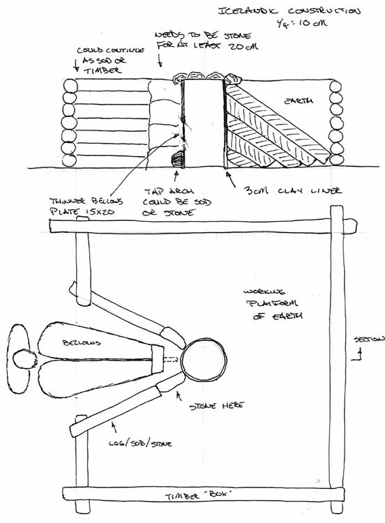
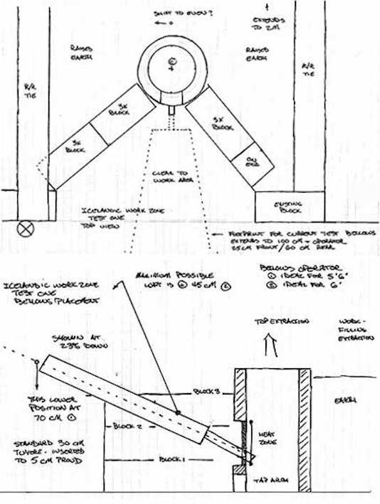
Figure 2 : Possible reconstruction based on Háls
(modified for beter function from Smith's orginal proposal)
The first consideration was attempting to estimate the
height required for a functional furnace. The excavation of the
furnaces remaining at Háls suggested a minimum angle to the
stacked turf blocks of 30 degrees, extending over a distance of
roughly one metre from the centre of the shaft. It is likely the
angle at time of use would have been greater than this, allowing
for the expected slumping of the material over the centuries. Even
allowing for a reasonable increase to 35% would easily allow for a
shaft height of 70 plus cm, certainly enough as had proved
effective in other smelts. This would allow for 20 cm from the
solid bottom of the furnace shaft to the tuyere, and a good 50 cm
working height above this point.
The next consideration was to provide for mounting a bellows, something thought missing in the original reconstruction drawing. (Smith, 2005) In modern tests, air is commonly produced by electric blowers, and then distributed by long pipes or hoses, neither of which would have been easily accomplished in the Viking Age. (4) This use of modern equipment allows for the source of air to be most conveniently placed at some distance from the furnace itself. The need to mount the bellows close against the furnace can create specific functional problems through the operation cycle of a smelt:
The third consideration was how the furnace wall around the ‘bellows gap’ would be constructed. With volumes of clay available, this is easily enough to accomplish, but what are the alternatives?
The furnaces at Háls showed some use of stone, likely requiring some limited use of clay to fill gaps between these pieces. There appears to be a base level construction of stone blocks forming an extraction arch, which would be required to be topped by a longer slab, with small stones perhaps framing the tuyere. Turf strips could then be laid horizontally above this, supported by that slab. The evidence does not directly indicate a full stone wall in this part of the furnace. These stones may have been purposefully or accidentally removed during the extraction process, and because they would certainly have been hot, simply dragged out of the working area for simple safety reasons.
A major question is 'What was used to use for the tuyere end of the air supply system?'.
There is no evidence to date of clay tuyeres being used in Viking Age Iceland.(Smith, 2005) As detailed earlier, the combined situation of simple scarcity of clay within Iceland, and further the possibly poor qualities of what is available (as discussed below), should not make this surprising.
Another possibility might have been the use of heavy forged wrought iron. Again there is no archaeological proof for this. For reasons of expediency and consistency, other smelting experiments carried out from 2003 – 2006 had all used industrial mild steel schedule 40 pipe. Set as insert tuyeres (standard was starting at 5 cm proud of the interior wall) the thin mild steel would burn away to the furnace wall, eventually leading to significant erosion of a portion of the wall surrounding the tuyere point.
Heavy forged (even possibly cast) copper tuyeres are also a remote possibility. There is some fragmentary evidence from a site in Reykjavik that may hint to this. (Smith, personal conversation)
Related to the type of tuyere material was how that
tuyere might have been mounted to the furnace itself. There were
two possibilities considered :
First is the tuyere rigidly mounted into the furnace wall, for best function inserted beyond the inner surface, ideally by 5 cm.
Second, the tuyere set a short distance in front of the furnace wall, placed to match a hole of some size cut into the furnace, a method labelled ‘blow hole’. (Nissen, 2005) Although there would still be considerable radiant heat directed back from this hole, ceramic or metallic tuyeres, or even just a bellows nozzle, would not suffer any noticeable damage. It might even prove possible to construct a bellows nozzle of a merely heat resistant material, such as a hard wood type, thick bone, or antler. The clay fragment recovered at Háls, suggesting just this kind of blast hole may imply at least some use of this air delivery method.
“ If this is what the fragment represents, the indication is for a hole diameter roughly 4 - 5 cm. With the usual 1 cm clearance, this would suggest an external (tuyere) diameter of 2 - 3 cm, certainly within the range possible if a metal tube was employed. Nissen has reported on his use of a tapered iron (mild steel) tube. He has good results with an air pipe outlet diameter in the range of 1.5 to 2 cm, working in concert with a blow hole in the range of 2 to 4 cm. This hole diameter in the bellows plate is based on a number of finds he has examined in Denmark. “ (Markewitz 2008a)
The Experimental Series
There were eight experiments in the Icelandic Háls series. Within the sequence, there are smaller groupings attempting to address specific questions or problems. As there were other experimental series being undertaken within the same 9 years, elements from other experimental discoveries (or outright improvements) would be incorporated into the Icelandic progression as well.
The weather at the test site in Wareham (roughly 125 km northwest of Toronto) averages from 20 C in June to 0 C in early November. All work was undertaken out of doors, under simple overhead cover, but regardless of rain or sun, with light winds typical.
The air volumes given are very rough numbers, based on
air speeds measured at the output from the high speed electric
blower used for all these experiments, then calculated
mathematically. Air volume into the furnace is controlled using a
sliding plate which blocks differing amounts of the output. Using
earlier measurements, this plate has been very roughly marked to
100 LpM increments, and these are the numbers recorded here. (Tests later in 2021, using better instrumentation, indicate these values are inflated by roughly 20 %)
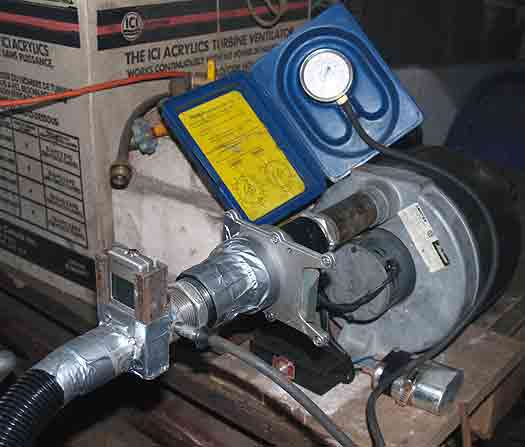
Figure 3 : Air Control System : Analog Test, 2008
Two other restrictions on materials were imposed by
the difference in geography between Iceland, and the work site in
Central Ontario. Wareham sits on top of the upper edge of the
Niagara Escarpment. This is a massive block of limestone,
extending some 750 km from top to bottom and a similar distance
side to side. There is no naturally occurring bog iron ore in this
entire region. Travel from Wareham a good 100 km to the north east
will place you into the bottom edge of the Canadian Shield,
composed of often exposed granite, with the possibility of finding
bog ore. Basalt, the bedrock underlying Iceland, is only found on
the extreme eastern edge of the Atlantic in Nova Scotia, easily
2000 km away.
The charcoal used for the experiments was primarily oak for the earlier tests, changing to maple by the end of the set. This primarily due to the twin dictates of changing availability and cost (A typical smelt used 80 to 100 kg (before breaking), at a cost $160 to $250 CDN)
The information below lists just the primary data. For more detailed descriptions, sequence data, layout drawings and photographs in process, refer to the links provided at the references section.
Icelandic One and Two (October 2007)
Main tests : Stone slab construction / tuyere at blow hole
Icelandic One consisted of a
partially earth banked, clay walled, cylindrical furnace, with a
large section of flat stones forming the majority of the front
face, which extended fully side to side and to 30 cm above the
tuyere. These were arranged to create a rectangular opening
roughly 5 cm tall by 6 cm wide. Into this a 2.5 cm ID steel pipe
tuyere was placed, resting to match the outer edge of the stone
face.
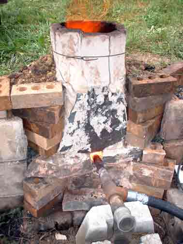
Figure 4 : Icelandic One during smelt
Furnace ID : D shape - 24 cm
Base to Tuyere : 20 cm
Stack above Tuyere : 55 cm
Wall Thickness : stone slabs 4 cm / clay walls 7 + cm
Tuyere Angle : 22.5 degrees downwards
Slag Control : left in furnace = slag ‘room’
Air Volume : 800 LpM
Charcoal Amount : 53 kg
Ore Type : Hematite blasting grit @ 68 % Fe
Ore Amount : 11 kg
Bloom : 2.7 kg
Yield : 24%
The primary information gathered on this experiment was the erosion effect to the inner surface of the stone slabs surrounding the tuyere point. These slabs were of schist, likely to have different heat resistance than Icelandic basalt. By the later part of the smelt sequence, the large slab located above the tuyere had heated visibly to an orange colour. When the cold furnace was dismantled, the original 4 cm thickness had melted away to about 1 cm in the circle just above and around the tuyere point.
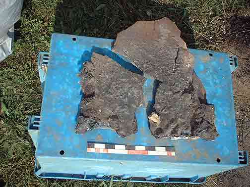
Figure 5 : Inner side of the upper stone slab after
the smelt, showing erosion
The hematite blasting grit used for this test contained low silica (only 1.2%) so as a result generated little slag. What was produced would have come mainly from the melted stone. As a result, there was no need for any tapping, the 20 cm tall area of the furnace below the tuyere easily contained the slag volume. The hematite was also known from previous use to be a very rich iron source, so the high yield despite the considerably smaller volume of ore used was not entirely surprising.
One aspect that mars placing this early experiment in sequence is that the notes come from a time before standard recording methods had been established. The rough field notes show a combination of Imperial and Metric measurements, some quantities that were given as volumes, in later experiments would be recorded (more correctly) as weights.
Icelandic Two was built of stone slabs (schist), partially earth banked, the only furnace in the series that was rectangular in cross section. The front pieces were arranged to create a rectangular opening roughly 5cm tall by 7 cm wide. Into this a 2.5 cm ID steel pipe tuyere was placed, mounted roughly flush with the inner surface of the furnace shaft.
One important experimental element here was the deliberate use of lower air volumes, thought to be more consistent with what would be produced using a bellows of possible Norse double chamber type, and size consistent with smelting furnace requirements.
In an attempt to ensure the correct amount of slag,
the richer hematite grit was cut with a quantity of what had been
proven to be high silica / lower iron content limonite (rock) ore
from Lexington, Virginia.
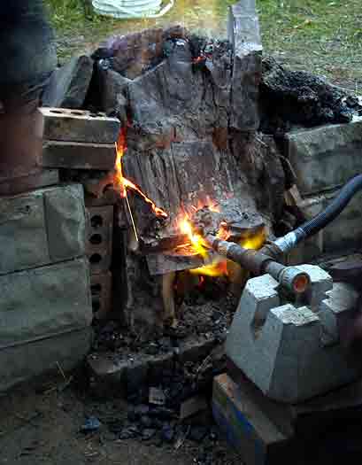
Figure 6 : Icelandic Two, showing hot air blow back,
stone cracking.
Furnace ID : (rectangular) 35 cm wide x 25 cm deep
Base to Tuyere : 18 cm
Stack above Tuyere : 40 cm
Wall Thickness : varies
Tuyere Angle : 26 degrees down, shifts to 10 degrees down over smelt
Slag Control : left in furnace = slag ‘room’
Air Volume : 400 LpM
Charcoal Amount : not recorded (170 L)
Ore Type : hematite with limonite – estimated 65 % Fe
Ore Amount : 12 kg
Bloom : 2 kg (fragments)
Yield : 17%
As should have been fully expected, the combination of lower air volume, coupled with the position of the tuyere tip at the outside edge of the stone slabs, resulted in less than ideal penetration of air into the volume of the furnace. Combined with the rectangular shape, this resulted in a D shaped burning pattern, the flat side centred on the tuyere point. The net result was that the two rear corners of the furnace were not ignited. This also caused any ore falling down through the upper column in the rear corners of the furnace were found to be at best only partially reduced, and not involved in bloom formation.
The reduced air volume also had the effect of greatly increasing the burn rate (time to consume a measured amount of charcoal) so also time between individual ore charge additions. Instead of the desired 8 to 10 minutes between roughly 2 kg charges, the interval proved closer to 20 minutes. This in turn meant that individual ore particles would spend much longer, after being reduced, inside the high carbon environment in the column above the protective slag bowl. The fine particle hematite ore had already proven in previous experiments a tendency to absorb large amounts of carbon (sometimes even causing the creation of high carbon cast iron).
As could have been predicted, the combination of the furnace only being fully ignited, with the tendency of the hematite ore to produce higher carbon, combined to result in a much smaller yield. The iron produced being fragmented, having a crumbly texture, and spark testing to a high carbon content.
Icelandic Three, Four (October, November 2008), Five (May 2012)
Main Tests : working dynamics / bellows plate & blow hole
The major shift with this group of experiments was
creating a working space that represented that illustrated at
Háls. The layout of the iron smelting area at Wareham is with a
low reinforced earth wall, about 55 cm high. On top of this, two
wooden beams and a line of stones was placed to mark the same 2 x
2 metre outline suggested as the timber framing at Háls. With this
space filled with earth, this created a flat working
platform at height of 65 cm above the front base level,
again resembling what was thought to exist at Háls. Furnace shafts
would be placed in the centre of this space. The triangular space
leading into the furnace was largely determined by the most
effective use of concrete blocks on hand used to contain the
modified earth bank.
 | 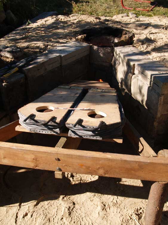 |
| Figure 7 : laying out the working dynamics space | Figure 8 : the fit of the frame that supports the ‘smelting bellows’ |
There was a significant shift in smelting experience both before, and certainly within this group of three experiments. Between fall 2007 and fall 2008, Markewitz would conduct an additional 9 smelts, importantly including participation at the ‘Iron Smelt at Thy’ workshop event at Heltborg, Denmark. This would include a number involving the bellows plate and blow hole system.
Over the same period, the DARC team would develop an analog for primary bog iron ore, with at least three smelts being tests of this material. The main ingredient was commercially available Fe2O3 red iron oxide. Attempting to mimic the known composition of the ores uncovered at L’Anse aux Meadows, it was discovered that adding 10 % whole wheat flour to the fine oxide powder would also serve as a physical binder. The resulting lumps had a similar porosity to that natural bog ore, with a roughly similar overall iron content (at 50 – 55 % Fe, depending on mixture). (Markewitz, 2009)
A third addition was significant research and physical construction related to bellows design. Lessons learned from the building of a number of smaller blacksmith forge sized units, based carefully on the two known Viking Age illustrations, would be enlarged to potentially produce the kind of air volumes needed for effective iron smelting.(Markewitz, 2019) Although this line of investigation is certainly ongoing, the current ‘smelting bellows’ build would influence the layout seen above.
Another change was the adoption of a standard ceramic tube tuyere. These were purchased as kiln shelf supports for porcelain, rated to withstand 1100 C. Each is 2.5 cm ID with 1 cm thick walls, the 30 cm long size used. This has proven both consistent, inexpensive and quite durable in use.
There would be the development of a standardized mixture for furnace walls. Early builds had used chopped straw, which was found to be sharp on the hands during mixing and often would cause noticeable breaks between the individual ‘brick’ shapes combined while stacking up the walls. Primarily from techniques learned from Micheal Nissen at Heltborg, the organic component was changed to aged and dry, then shredded, horse manure. The normal mix is one third high temperature ‘EPK Foundry’ dry pottery clay, one third course beach sand, one third of the manure.
Although not obtained from the Háls excavations themselves, a small sample of clay like material was gathered from the margins of the hot spring Deildartungahver 16 kilometers west of Háls in Reykholtsdalur, Iceland by Michelle Hayer Smith. In 2009, Hayeur Smith and Smith made crucibles from this clay, mixed approximately 50/50 with locally available basalt river sand, and fired them in an open birch fire at Reykholt, Iceland. In 2010, Hayeur Smith and colleagues from the Rhode Island School of Design used these crucibles to melt brass using both direct flame from an acetylene blow torch and with closer heat control inside a furnace. Although several of the crucibles began to deform and melt at or near the melting temperatures of the brass used (about 900 - 1000 C), others retained their form while becoming semi-elastic and then regained their strength on cooling. This test certainly suggested the potential suitability of an Icelandic sourced clay and sand mix for smelting furnace construction.
It proved possible to have part of this sample chemically assessed. The Icelandic material was found to be most similar to a form of bentonite, which is a type formed from weathering volcanic ash. The sample contained the primary components : SiO2 (52%), Al2O3 (14%), Fe2O3 (13%), CaO 9% and MgO 6%. As part of this process, consultation was made with a major commercial pottery supplier about the possibility of duplicating the components and properties. Although the formation of clay materials is complex, this points to the possibility of creating an artificial duplicate of the natural Icelandic type for use in further experiments.
Icelandic Three would be the first ‘working dynamics’ test inside the new layout. The complete bellows was placed for fitting of the air system, but against possible damage was lifted from its frame during the smelt, with the tuyere remaining place and using piped air from the electric blower. The furnace was built of clay cobb (horse manure), earth banked but for the exposed front wall. The air system used an inserted thinner clay bellows plate, 20 cm wide by 25 cm tall and 3 cm thick, with an 8 cm diameter hole. The reason for the thin plate is that heat will radiate off the surface, keeping temperatures from reaching the melting point. Again the standard ceramic tube was used as the tuyere, initially set with a gap of3.5 cm to the plate, later converted to an insert style.
Earlier smelts had used a top extraction method. In combination with this was the incorporation of a technique copied from early experimental work in the Netherlands, where a length of timber post was used to compact the hot bloom in place while still inside the furnace. (Boonstra, van de Manakker & van Dijk, 1997) It has been demonstrated that not only does this help compress to great effect while the metal is at its absolute hottest, the repeated impacts help to loosen the bloom from the encompassing slag bowl. With the furnace mouth essentially flush to the top working platform suggested for Háls, this would mean standing directly over the shaft of the furnace, fully exposed to, and reaching down into, the hot blast. For the balance of this series, top extractions were initially planned, but for various reasons never completed.
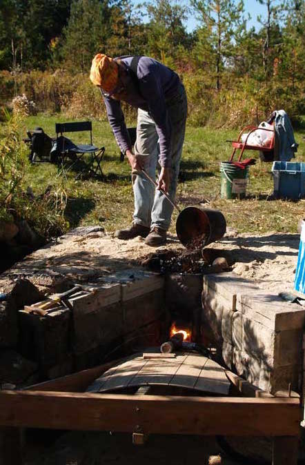
Figure 9 : Icelandic 3, Markewitz adding charcoal,
working on the platform top
(image by Neil Peterson)
Furnace ID : 22 cm
Base to Tuyere : 20
Stack above Tuyere : 45
Wall Thickness : 5 cm
Tuyere Angle : 15 degrees downwards
Slag Control : set for slag room, but ran incontinent after shift to insert tuyere
Air Volume : 600 LpM
Charcoal Amount : 46 kg
Ore Type : taconite with limonite – estimated 60 % Fe
Ore Amount : 23 kg
Bloom : 4.9 kg
Yield : 21 %
The limonite (with higher silica content) was added first. This, in combination with the difference in air penetration caused by the blow hole method, was thought to be the reason the developing slag bowl was forming too high in the furnace. The blast could be seen forcing liquid slag back from the bottom of the hole, which was slowly closing. Concerned that this might block the air flow entirely, the ceramic tuyere was pushed forward into the furnace to create the then proven insert style.
An attempt was being made to reduce clay wall thickness to approach that known from Háls. There was no noticeable impact at the 5 cm thickness, either in terms of building problems, cracking during drying, or failure during the smelt.
Icelandic Four was in many ways a repeat of the previous experiment. The air system was now supported by suspending it on chains from above, which did permit removing the bellows frame and making access to the front of the furnace far easier. The ceramic tuyere was replaced with a length of steel pipe, forged to a final taper. Unfortunately, no specific measurement of the ID was made, and this pipe has since been misplaced. Again a bellows plate was constructed and inserted into the front wall of the furnace, 18 cm wide by 24 cm tall, the blow hole at 5 cm diameter. The gap between tuyere and hole was set to 2.5 cm.
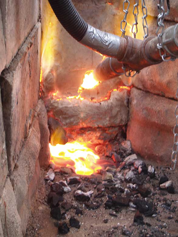
Figure 10 : Icelandic 4, self tapping near the end of
the smelt.
Furnace ID : 26 cm
Base to Tuyere : 20 cm
Stack above Tuyere : 42 cm
Wall Thickness : 5 cm
Tuyere Angle : 25 degrees downward
Slag Control : set for slag room, but ran incontinent
Air Volume : 500 increased to 1000 LpM
Charcoal Amount : 48 kg
Ore Type : hematite with limonite – estimated 60 % Fe
Ore Amount : 24 kg
Bloom : 3.3 kg
Yield : 14 %
Once again, the combination of higher silica limonite ore, lower air volume and less effective penetration via the blast hole caused the slag bowl to form too high in the furnace. The less obstructed working area (piped air and hanging tuyere set) did allow better direct manipulation of the slag bowl, with attempts made to probe holes into the bottom of the bowl so to let slag drain into the lower space. For this experiment however, rather than changing the tuyere position, it was decided to greatly increase the air blast. This was seen to have the effect of both increasing slag temperature, but also pushing the slag bowl back further into the furnace. As the shape of the slag bowl changed from the earlier ‘cupped up’ shape to a flatter surfacer this obviously also changed the potential flow of slag within the lower slag mass, resulting in self tapping during the last phases of the smelt.
Icelandic Five was also named ‘Return to Iceland’, as there had been a gap of four and a half years on the work for this specific series, with a total of 14 other smelt events in between. Important over this time was the ‘Vinland’ series, working to re-create that first iron smelt in North America. Beyond the general increase in experience with bloomery iron furnaces, use of the analog (called ‘Dark Dirt’) had become standard, at the least reducing the earlier variability injected to the experiments through the use of changing iron oxide types, physical qualities and even iron to silica concentrations between differing ores used in separate experiments. The specific mix used for this experiment had included 2.2 kg fine white silica sand, bringing the total of silica up to roughly 10 % in total.
The main elements repeated from the other experiments in this group were the use of a ground banked furnace set inside the Háls working layout.The clay walls were reduced again, this time to roughly 4 cm thick, with the shape slightly flattened at the front wall.
The tuyere was the ceramic tube, this time set tightly into the furnace, and extending beyond the interior wall 5 cm. The body of the furnace extended down 7 cm slightly below ground level, with a shallow trench leading away from the furnace. The design was intended as a slag tapping type, This trench was a sloping spoon shape in cross section, starting as wide as the furnace, at its deepest 11 cm, and extending forward 36 cm.
One problem with this specific experiment was the small working team, consisting of only Markewitz and Peterson. For this reason the notes kept are minimal, with less photographs that normal.
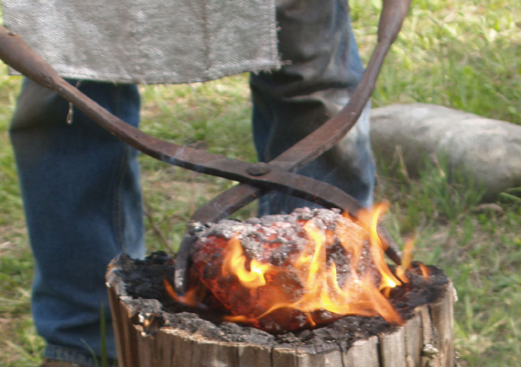
Figure 11 : Icelandic 5, the bloom as first extracted,
starting compaction on a stump.
(image by Vandy Simpson)
Furnace ID : slight D shape – 28 cm wide x 26 cm deep
Base to Tuyere : 10 cm
Stack above Tuyere :48 cm
Wall Thickness : 4 cm
Tuyere Angle : 22 degrees downwards
Slag Control : slag tapping
Air Volume : 800 LpM
Charcoal Amount : 49 kg
Ore Type : DD 1-S (red + silica) analog @ 50% Fe
Ore Amount : 32 kg
Bloom : 5.8 kg
Yield : 18 %
The early part of the year at Wareham can find the earth quite damp, the adjacent pond can almost be at the same level as the floor of the smelting area. The clay lining of this furnace was built and subjected to a drying fire within 24 hours, with the smelt itself started the following morning. It was found there had been considerable spalling off of fragments of the clay liner during the drying process. It was uncertain if this also might have been an effect of the thinner walls.
This was still an almost ‘text book’ smelt in terms of consistency of working sequence and predicted results.
Around the time of Icelandic Five, a long discussion was entered into with Margrét Hallmundsdóttir, an archaeologist from Iceland, as she prepared to undertake her own experimental test smelt, based on her research into Icelandic Viking Age prototypes. Importantly, the smelt her Greenvillage Grampus team undertook in Iceland, June 2012, represents proof of the viability of a full scale grass sod build, with their creation of a viable, if small, iron bloom at about 2.8 kg. (Markewitz, 2012b)
Hallmundsdóttir would start excavations at Auðkúlu in western Iceland in 2015. This is also a long occupied site, with clear indications of multiple iron smelting furnaces operated. Images of one furnace excavation (at base level) suggest a lower stone chamber surrounded by what was most likely a construction of flat laid strips of turf. (Hallmundsdóttir, 2021.) That experiment certainly suggested some potential problems to consider as our own series continued.
Icelandic Six (Fall 2014 to June 2015), Seven (October 2015), Eight (October 2016)
Main Tests : grass sod builds, reduce to eliminate clay lining
The next major component of the Háls evidence was to investigate the use of grass sod strips in construction. These were cut from the unkept yard close by the work area, at least simulating the correct Icelandic turf. (5) For the first two experiments, the same earth bank area of earlier experiments was used, digging down to enlarge the hole in the centre. This would mean the individual pieces ofgrass sod would not be the full diagonal lengths indicated by the turf in the archaeology. The reason this was done was to avoid the expense of purchasing timber, and to limit the volume of grass sod required (and considerable work cutting this). Rough calculation estimated that with sods cut to 10 cm thick, some 13 square metres of surface would need to be cut up for the full diagonal strip build. The use of the shorter lengths reduced this requirement to less than half that amount. As the suggested build at Háls also was earth filled, this difference was not deemed necessarily significant.
The last experiment would be a full scale self supporting structure contained in a timber frame, as seen at Háls.
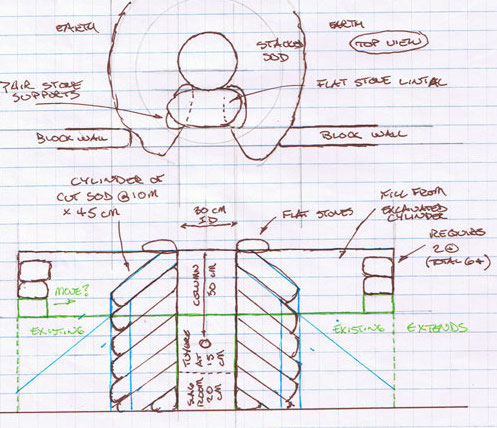
Figure 12 : theoretical construction layout for
Icelandic 6 and 7
Icelandic Six had the construction to finishing steps extended from late fall 2014, over winter, to completion in spring 2015. Once a suitably large hole had been cleared, a V shaped stack of solid clay bricks (simulating flat stones), topped with a wide stone slab, was positioned to create a combination tapping and extraction arch. During the smelt, this arch space would be sealed with sods. The interior (furnace side) of this arch was 18 cm wide by 20 cm tall, opening to about 40 cm wide (notes unclear). Against this was placed a cylindrical sheet metal form at 35 cm diameter, which would make controlling the inner profile of the furnace easier while stacking the grass sods.
The first ring of grass sod pieces were all fairly short, in the range of 15 cm long. The next were longer, to about 30 cm, with the third layer reaching the full length of 45 cm used for the rest of the construction. Strips were cut to a taper as they were stacked up, with the resulting triangles used to fill the gaps, with other cut pieces fitted to make the overall cylindrical shape.
At the front part of the furnace, the wall thickness could only be as much as the lintel stone was wide, in this case averaging 33 cm. This resulted in the strips here being laid more or less horizontally. This front wall would be about 30 cm thick for the first 40 plus cm, tapering thinner as it approached the top of the furnace. Once the top inner edge of the stacked strips reached to a total of about 80 cm, the remaining gap between the initial hole and the sods was filled with earth and lightly tamped down underfoot. Further, a ring of flat stone slabs was laid around the upper mouth of the furnace.
The tuyere was the standard ceramic tube, set initially to 6 cm proud of the furnace interior. This was placed with the inner edge resting on the stone slab, wedged with a small piece of sod to approximately the usual angle.
Key to this experiment was that no clay would be incorporated at all, either to seal the arch stones, or more significantly, as an inner liner to the furnace shaft.
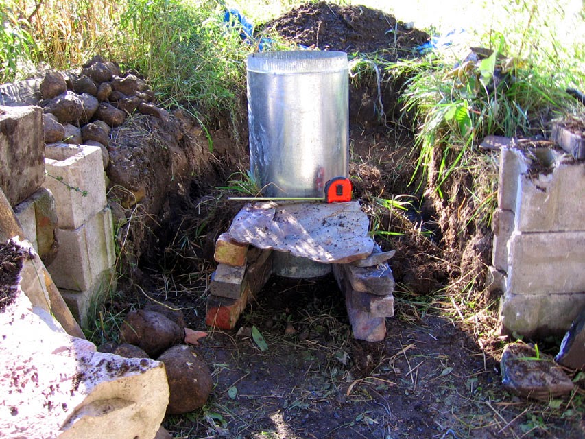
Figure 13 : Icelandic 6 during construction, showing arch stones
Furnace ID : 36 cm
Base to Tuyere : 24 cm
Stack above Tuyere : 50 cm
Wall Thickness : no clay used
Tuyere Angle : 22 degrees downward at start, shifts to 12 down by end
Slag Control : left in furnace = slag ‘room’
Air Volume : 1200 plus LpM
Charcoal Amount : 76 kg
Ore Type : DD 1 analog @ 52% Fe
Ore Amount : 31 kg
Bloom : 7.7 kg
Yield : 25 %
When this furnace was initially laid out and construction started, the intent was to again add a thin clay liner. The twin limitations of available time and poor weather did not allow for this. One significant impact on this change would be increased internal diameter, from the 30 cm range of other smelts to the effective 36 cm ID here. As ideal air volume is a cube function, even a small increase in diameter can have serious effects on effective air delivery inside a furnace. In this case the ‘ideal’ amount was at, if not beyond, the upper possible limit of the blower used. For this reason, the air volume used was higher than previous tests.
One very important observation from this experiment is that the clay liner is not actually required for the furnace to function, at least for a single smelt event. What was observed is that the charcoal itself appeared to help support the inner walls of the furnace. As the furnace was allowed to burn down however, there was considerable slumping of especially the upper part of the inner walls. The heat had burned away the supporting grass roots of the sod, leaving a pile of loose, dry, sandy soil to collapse. This did not seem to cause a major problem with a single smelt event, but might prove to be a major problem if a second attempt to fire this furnace was made – at least without significant repairs.
The difference between diagonal, earth banked lines of grass sod and the narrower, flat layering at the front gap of the furnace became clear. There was noticeable venting of hot gasses through the grass part of the sod layers at the furnace front. This did not appear to alter the effectiveness of the smelt, other than how it might have caused some loss of reactive gases inside the working reduction system.
The drying and crumbling of grass sod used to support the tuyere did result in the original angle shifting, but this was thought to be easily controllable by simply using small stones instead.
The crumbling of the inner walls during the smelt certainly was found to lead to the production of more slag than expected. The space provided below the tuyere did allow for the developing slag bowl to settle as desired, allowing for the space for a good sized bloom to develop. At the extraction point however, it was found the slag had formed much higher at the rear part of the furnace than normal. This likely a result of not only an additional volume of slag, but also because of the air flow dynamics in this larger diameter. Although an attempt was made, in the end it proved not possible to extract the bloom with the furnace hot. The entire furnace was dismantled later, which would provide some insight into the formation of the entire slag bowl system. Working cold, the slag mass would be shattered under sledge hammers to free the bloom.
Icelandic Seven was a new build, similar in general outline to Six, again diagonal grass sods banked by earth. On this experiment however, a thin clay liner was added, about 3 cm thick. There had been more and more of a problem getting the wet clay to remain in place as the walls got thinner in previous experiments. On one side was the loose soil caused by the limited penetration of roots through the grass sod strips, on the other was the tendency of the wet clay to stick to hands as the material was applied. The net result was that any attempt to get the clay much thinner than 3 cm was just not allowing the clay to stay in place.
The internal liner was constructed in stages. First two or three layers of grass sods were stacked inside the larger hole, set against the metal form. The form was pulled clear, then clay was applied to a height of about 30 cm. When completed, the interior space was filled with a loose packing of dry wood ash mixed with course sand. One purpose of this fill was to help stabilize the damp clay, keeping it from slumping in place. The metal form would be placed above that clay ring, and another two layers of grass sod fitted around the outside. The sequence of applying clay, then packing, was repeated. This process was undertaken three times in total, allowing the full height of the clay liner to be completed to 79 cm. The ash and sand mix also serves to draw moisture out of the damp clay. Later this material was all scooped out from both the top and out of the bottom tap arch before starting a drying fire. As the clay was found still to be fairly damp this initial drying was accomplished by inserting a large propane burner, pointed upwards, in through the tap arch. An additional layer of grass sod, again with the top opening framed with flat stones, would increase potential stack height, + 16 cm at the front, + 28 cm at the rear.
Again commercial clay bricks and a stone slab outlined the tap arch, at 20 cm wide and 21 cm tall. During the clay built, a block of wood was cut that size and placed to support the bottom of the liner.
The tuyere was again a ceramic tube, set 5 cm proud of the furnace interior wall. Learning from last time, the tuyere angle was supported on a flat stone block. This was set fairly high above ground level, with 10 cm deep bed of charcoal fines defining the base of the furnace. This space was intended to collect excess slag without the need for tapping. Again, by the final stages of the smelt it proved necessary to tap excess slag to keep the tuyere clear.
One addition to this experiment was a provision to take internal temperatures over the course of the smelt. Neil Peterson had come equipped with a set of rigid high temperature thermocouples. These were set along one side of the front gap of the furnace, at 28 / 38 / 51 / 67 cm above ground level.
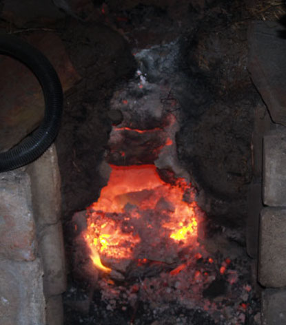
Figure 14 : Icelandic Seven, just before the
slag bowl mass was broken to expose the bloom, the front furnace
wall largely broken away.
Furnace ID : 29 cm
Base to Tuyere : 14 cm
Stack above Tuyere : 66 cm (taller to rear)
Wall Thickness : clay liner at 3 cm
Tuyere Angle : 22 degrees downwards
Slag Control : left in furnace = slag ‘room’
Air Volume : 1000 LpM
Charcoal Amount :56 kg
Ore Type : DD 1A analog @ 54% Fe
Ore Amount : 30.5 kg
Bloom : 4.3 kg
Yield : 15 %
Almost from the start of this experiment, it was clear the heat was not penetrating back through the entire furnace volume, but the interior was staying visibly hotter towards the front wall, above the tuyere. Throughout the smelt, even with the air increased, the burn times for a standard bucket (1.8 kg) were averaging 14 – 15 minutes.
Again the plan had been for a top extraction. Between falling temperatures and the size and form of the slag mass, it proved impossible to work the bloom free from above. Quickly switching to a bottom extraction, there ended up being a lot of damage to the front of the furnace caused when working the bloom free.
Icelandic Eight was a full scale free standing prototype of the Háls system, with the exterior timber frame measuring (estimated) 200 by 200 cm. DARC member Richard Schweitzer had volunteered to undertake the build at his (larger) rural property outside Laurel, Ontario (about one hour NW of Toronto). He would also serve as ‘smelt master’ for this test, which would be his first full attempt at undertaking a build and managing a smelt. One unfortunate result was that the record keeping was much more random than normal, most of the measurements reported here had to be estimated from (limited) photographs. In truth, the overall effort should be considered more experiential than experimental.
Once again, the tap / extraction arch was built up of stones with a large slab lintel, the opening (estimated) at 28 cm wide by 20 cm tall.
The soil from which the grass sods were cut was quite sandy, resulting in an even less dense root mass, especially to the lower side of the roughly 10 cm thick slabs. The build was undertaken without the use of a central form (as in Six and Seven). There was also considerable settling of the grass sods as the layers were stacked higher. Combined, this created a quite irregular central shaft shape defined by the rough surface of the grass sods.
Individual plate shapes of wet clay were applied to this inner surface, working reaching down from the top into the cut hole. The sand content of the grass sod strips as cut became a problem, making it difficult to get the thinner clay to stay in place. Only enough clay was on hand to extend the clay liner for the bottom 60 cm, the upper 18 cm would be framed with the grass sods alone.
The end result of all this was both variations in the clay liner’s thickness, and that the central opening of the furnace shaft was distorted to a quite irregular shape.
The weather during the build had turned wet and cold. For that reason, there had been very little natural drying of the clay. The normal practice of using a slow, small sized drying fire before smelt day was not undertaken. This process was started on the morning of the smelt, and pushed due to time limitations. As a result, there was excessive damage due to steam spalling, flaking off large pieces of the clay liner. Falling to the bottom of the furnace, these fragments would significantly reduce the room initially left for the developing slag bowl, creating in effect a hard base at 11 cm below the tuyere point.
The tuyere was a heavy forged copper taper with 2 cm ID. This was mounted through the grass sods stacked above the stone lintel, through a matching hole cut into the clay liner.
Another potential moisture effect may be indicated by the charcoal weight as recorded. The standard ‘bucket’ measure of broken for size maple charcoal typically weighs about 1.8 kg, but the notes indicate for this experiment the measured weight was almost 2.0 kg. (Charcoal will absorb moisture from the environment when stored out of doors.)
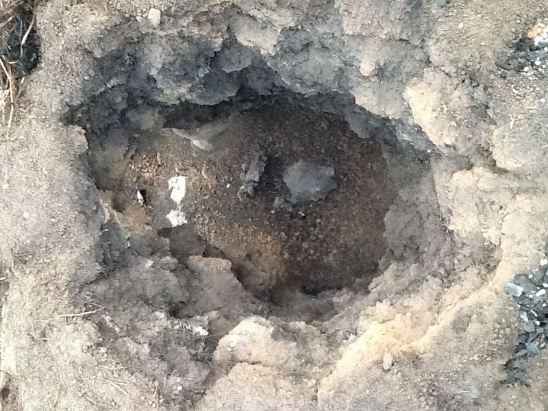
Figure 15 : Icelandic 8, the furnace interior after
the smelt, showing the clay liner now completely absent.
(image by
Richard Schweitzer)
Furnace ID : irregular tear drop shape, 13 cm at the tuyere, 26 cm wide at the back, by 33 cm deep
Base to Tuyere : set for 17.5 cm, clay debris reduces to 11 cm
Stack above Tuyere : 37 cm
Wall Thickness : 3 cm (photographs suggest 5 cm)
Tuyere Angle : 25 degrees downward
Slag Control : tapping
Air Volume : 1200 plus LpM
Charcoal Amount : 63 kg
Ore Type : DD1 analog @ 60 % Fe
Ore Amount : 25 kg
Bloom : 2.5 kg
Yield : 10 %
Over the course of this smelt, maintaining effective air flow and controlling slag would be major problems. The combination of the pinched shape, too little available space below the tuyere, the exposed, loose sandy soil on the grass sods, would all combine to make for a slag bowl sitting too high, and more slag formed, than in other tests.
The front wall section of the furnace experienced considerable heat damage effects, and had to be repaired with additional sods and timber bracing.
Despite the extremely high air volume used (the blower running wide open), the average burn rate per charcoal measure was still about 15 minutes. It was clear there was not effective penetration into the furnace, with the distorted shape considered one of the major factors here.
One important lesson from this full scale build was
altering the idea that a flat platform was always needed as a
working area close to the mouth of the furnace. The already
existing handles on the ore scoop and charcoal bucket (originally
added as a safety feature for working over the hot top of the
furnace), combined with the arm length of the adult workers,
proved more than enough extension to allow these individuals to
stand on the ground outside the frame, yet still reach effectively
to the interior. Any probing to settle charcoal certainly had to
be done from on top of the furnace platform. The original intent
was for a top extraction, which certainly would have to be
undertaken from the platform surface, but the position of the slag
bowl resulted in a bottom extraction being attempted instead.
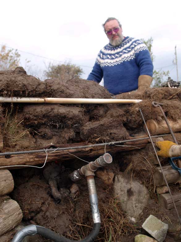
Figure 16 : Peterson preparing to add charcoal while standing outside the furnace frame
Looking at Results
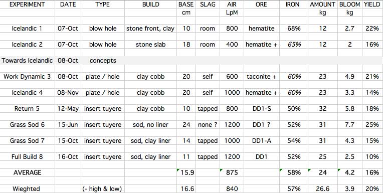
Table 1 : Major experiment elements to results
In combination with this sequence of experiments, other related work at the time, and that carried out since 2016, has added to both an understanding, and practical experience with, bloomery iron smelting in general. Looking at a simple charted format of what are deemed the elements that might have the greatest impact over this group of eight experiments, no clear pattern is obvious.
Any attempt to re-create lost physical techniques through the use of experimental archaeology always invites comparisons and contradictions. This is especially true when undertaking early methods of bloomery iron smelting, where most typically the ancient remains are so limited, both in number and in completeness. Háls is significant, and unusual, in that so much of the furnace superstructures remain. Even still, elements critical to functional production of iron blooms are clearly missing.
Most important are the lack of any clear indications of the elements of the air system, on which the entire process depends. Early in this series, the focus was on an alternative to the insert style of tuyere. The first four experiments were all variations on this type, using a ‘blow hole’, either a gap in front stones or as a separate clay plate. There does not appear to be any specific impact on iron production, at least on first consideration. Considering only Háls, only one small clay fragment might suggest use of some form of clay plate defining a blow hole arrangement. There is no surviving evidence for any other mounting of a tuyere, or what material the air supply tube was made of. A principle that must be remembered however is ‘Absence of Evidence is not Evidence of Absence’.
With a large number of experimental smelts now in hand employing insert style ceramic tuyeres, there is at least good quantitative experience by this team on what could be expected to survive after use of even a high temperature rated ceramic. These have been seen to experience significant (and telling) erosion, as well as becoming coated with glassy slag. At least the final 5 – 10 cm of even a raw clay tuyere would have been exposed to enough heat to sinter it to ceramic. It is considered that it was extremely unlikely , given the very large number of individual smelting events indicated by the large volume of slag recovered at Háls, that none of this kind of durable object would have survived. This certainly can be taken as an indication that this type and method were not employed at Háls.
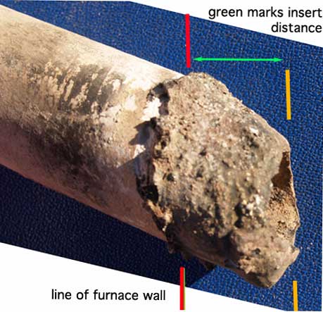
Figure 16 : High temperature rated ceramic tube, after
a single smelt use.
Note how the erosion at the tip will be
vertical, so the insert angle can be estimated.
As previously mentioned, repeated use by this team and
others has shown that a heavy walled copper tuyere suffers almost
no physical damage at all, even through repeated use. (6) A tool
made from such a large mass of copper would have had intrinsic
value and, in Viking Age Iceland, could only have been obtained by
trade since there are no natural sources of copper, zinc, or other
non-ferrous metals in Iceland. If not the continued use for this
specific function, certainly as raw material for creation of
bronze alloy to be used in fine metalwork casting. Given the hole
diameter (5 cm) of the curved clay fragment found, the slag
coating might easily suggest this was in fact from clay used to
seal around a copper insert tuyere. There might be no further
indication other than this kind of size and shaped impression
remaining after such use.
Use of a wrought iron tuyere is another possibility. One significant consideration is that the modern mild steel material forming the tuyeres used in early tests has a lower melting point (at 1350-1540 C) than wrought iron (at 1480 – 1600 C). In practice, the ‘burning point’ inside an air blast, causing erosion, is effectively lower than these temperatures. Sauder has described a heavy forged wrought iron tuyere, based on an object recovered from a ‘traditional’ side blast blacksmith’s forge. He also reports uses of his reconstruction, inside a bloomery furnace :
“ I have only used this tuyere twice in the bloomery furnace so far, there is no measurable loss, and it performed quite well. In general, the bloomery is a much kinder environment for the tuyere than the forge is- despite the higher temperatures, the environment is much more reducing, and the tuyere gets protected by a nice thin film of slag. “ ( Sauder, nd.)
There certainly is not enough information available at this time to understand the working durability of an iron insert tuyere, or what (if any) visible impacts this use would have on furnace remains through to possible archaeology. As with copper, a specially formed tool would have a high relative value. Although greater erosion during frequent use would be expected, the starting weight of a wrought iron tuyere such as suggested by Sauder represents about 3.5 kg of material. Iron objects beyond their original use can be, and most certainly have been, reworked into new objects over time.
It was certainly demonstrated through the first experiments in this series, where natural stone was used to frame a blast hole, that there were major visible effects on the stone involved, both in terms of erosion effects and slag coating. Although air volume and especially delivery pressure has an effect, our smelts show a similar pattern of heat induced effects on furnace interior walls. The typical pattern is an oval around the tuyere point, extending roughly 10 cm side to side and upwards about 15 cm. The lower edge can vary, as the formation of the slag bowl changes that distance, but typically 5 to 10 cm below. This oval will be larger with high air volumes, smaller with lower air.
Although high temperature effects on the stones recovered in the excavation might provide some clues, most often hot stones are quickly tossed to one side for worker safety during bloom extraction. These might end up being reused in some other position entirely in later construction, or later removed as debris to clear the working site. This all limits the amount of information that might be interpreted.
The overall conclusion of all this is that hard evidence should be fully expected to be extremely limited. The exact method used to deliver air into the furnaces built at Háls may never be proven.
The single largest departure from a possible Viking Age process is seen in these experiments with the use of a clearly modern electric blower system. The primary reason for this substitution is the massive allocation of labour needed to merely operate a Norse type bellows, at a measured and consistent rate, over the many hours required for even a ‘smaller’ 25 – 30 kg ore smelt. (7) The team’s experience over the Vinland experiment series (2009 – 2010 plus 2017) suggested a dedicated group of four individuals were necessary just operating the bellows. (Markewitz - 2010)
As detailed earlier, the way air is distributed inside the furnace is further modified by how the available air volume is applied into the furnace itself. Ideally the supplied air will penetrate into the entire volume of charcoal within the interior. It also is important for the formation and position of the slag bowl, and the developing bloom within it, that air also be directed downwards. There should be enough force to push the effective ‘hot zone’ back towards the centre of the furnace, both for full involvement of the entire volume of charcoal, but also to push the highest temperatures away from the front wall, reducing erosion.
Over a number of tests (both detailed here and before) it was observed that the blast hole method resulted in far less penetration away from the front of the furnace. The end result was a slag bowl forming much higher inside the furnace. It certainly is possible to control this high level, but this requires careful and constant manipulation of the developing slag. Additionally, this method does not force the air as completely into the furnace, which in turn shifts the hot zone closer to the front interior wall. The possibility of overheating and significantly eroding the front wall certainly exists, a problem with thicker walled structures. One way to control this effect is to build using a thinner, more heat resistant material, which has been discussed as the basis on which the thin bellows plate functions. This can also be accomplished by use of a thin stone slab, this is suggested as the most likely method employed at Háls. Such thermally-stressed slabs would be most likely to suffer breaking to smaller fragments over centuries of freeze and thaw, and would be less likely to be recovered as intact items in excavation.
Another effect of a high, narrow, and shallow slag bowl is that it does not leave much room for the bloom to develop. Without any intervention, the iron will form into a crescent shape, the centre poking through the protective slag. The air blast, at the kinds of temperatures involved, starts acting just like a cutting torch, eating away at the iron as fast as new reduced material is deposited. This could be at least somewhat controlled by opening the arch below the slag bowl, and tapping hot slag into that space, allowing the entire bowl to sag downwards. All of this poking and prodding of the slag requires however that there be easy and frequent access to the front of the furnace. Again this raises the question of just where the bellows might be placed, and how it might be physically attached to the tuyere, especially if an insert type. It might be possible to set the bellows exhaust tube just proud of a blast hole, then repeatedly lift out, work quickly, then replace the whole unit. Experience has shown however that it does not take much interruption in the constant air blast to allow the furnace interior to drop below effective smelting temperatures. The liquid slag cools and freezes, and then it is almost impossible to get the interior temperature back to the levels required.
One question that always emerges when looking at re-created smelts is ‘What about the quality of the iron?. Excavations at Háls itself did not recover any finished iron blooms. This of itself is not surprising, as these masses of iron had a high intrinsic value, if only a reflection of the effort, specialized skill and raw materials expended in their creation. Within a Viking Age context, ‘quality’ is expected to mean something quite different that might be the objective of a modern maker. (8) To these early Icelandic iron masters, a soft, relatively carbon free iron would be highly desirable, as this is a material most easy to render to the widest range of objects in a blacksmith’s forge. It is often forgotten the end product would not be the bloom itself, but that mass rendered down to standardized working ‘currency’ bars. Recent work by these authors on that second processing step has shown that dense blooms, with few voids and containing little slag, can have a major impact on both the ease of work, and importantly, on reducing the losses during the compaction, folding and welding required to produce suitable stock bars. (Markewitz, 2018).
Raw bloom size of itself is not a measure of
‘quality’. In actual fact, the smaller size of known Viking Age
forges and general blacksmith’s tools (notably anvils) would
restrict just how large a physical mass of iron that could be
re-heated, and then effectively worked under a hand held hammer.
(9) Importantly the larger the bloom, the larger the forge needed
to heat it, and the more difficult it will be to raise that mass
up to the required ‘welding’ temperature. Larger bloom masses, at
the upper limit suggested by Smith, would most certainly also have
required that large earth set stones would be needed as anvils.
This requirement does conform to the evidence found at Háls.
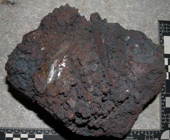
At least the excavated furnaces at Háls (admittedly evidence from only the last use in a much extended production effort) illustrate a distinctive gap in the slag bowl given as roughly 15 cm diameter by 5 – 10 cm deep. The bloom pictured above, which at this point has only been quickly hammered at extraction to knock off loose clinging slag, is seen as 18 cm long by 14 cm wide and 7.5 cm thick. It is of reasonable density, and weighs 3.5 kg. Clearly these last extracted blooms at Háls must have been in the 3 - 5 kg size range. Based on past work by this team inside similar diameter furnaces, a bloom of 8 kg could be expected to measure roughly 23 cm in diameter by 10 cm thick. Obviously it appears possible that the Háls system should be able to create such large masses. Getting such large blooms out of these furnaces, without seriously damaging them, would prove quite difficult however. Some consideration of the two possible extraction methods is required. Is it possible to extract these larger blooms through the top of the furnace?Alternatively, exactly how a suitable extraction arch would be constructed to allow for bottom extraction without extensive damage? A third possibility might be some kind of continuous batch method, where a number of smaller blooms were created and extracted one after the other (from the top) within a longer smelting sequence, as seen the later ‘Evenstad’ method. (Espelund, 1997) Interestingly, the partially refined blooms found in a cache beneath the wall of a Viking Age structure at Vatnsdalur, northwest Iceland, weighed 3-5 kgs each. Depending on how much work had been done on these blooms, their original weight on extraction from the furnace might have been in the range of 4 to 6 kgs, perhaps more plausible for the Háls-type furnace.
In Smith’s original paper describing Háls, he had suggested possible yields from smelted ore at Háls as 20 %, a figure primarily based on early estimates of bloomery furnace results from the work of Peter Crew (Smith, 2005, Crew 1991). It is perhaps ‘elegant’ that when the lowest and highest numbers from the individual smelts are removed, the resulting average yield from this test series is also 20% return.
In this series of smelts, there were alterations of
ore body, air delivery system, overall furnace build, slag control
method (even air volumes!) between individual tests. This clearly
illustrates violation of a fundamental experimental principle :
Only change ONE variable per test.
Two aspects behind the entire series caused this:
First – what is profiled here was a series of related, but in many ways, individual, experimental tests. There was never an overall outline or encompassing plan established at the beginning. Given the time between individual tests, most often the process was more a number of individual decisions made on ‘what’s next?’, rather than a defined long range outline.
Second, the limitations of (limited) private funding come into play. Recent calculations of the cost of just raw materials expended on each smelt total some $350 CDN, not to mention approximately 50 + work hours. For these reasons, there was considerable pressure to ‘just make things work’. On a number of occasions there were major modifications made to equipment, or process, in an attempt to recover what was clearly heading to a failed effort, a drive to ensure there would be effective iron production. The best example of this might be Icelandic 3, when the blast hole was converted to insert tuyere, or Grass Sod Build 8, when air was increased well beyond amounts even remotely possible to to deliver using Norse bellows.
Another problem becomes apparent when looking backward to work carried out in some cases 15 years in the past. This is the importance of developing, and maintaining, a detailed and standardized reporting framework. (Markewitz - 2020) This may be blindingly obvious to trained archaeologists reading, but even in modern experimental work ‘Once you’ve done it – its GONE’. This became clear in the preparation of this report. A good example here is that the charcoal is added using a ‘standard bucket’ measure. The original recording of charcoal additions for experiments 1 and 2 of this series was as volume in litres. This then changed to recording by ‘buckets’, where one such bucket amount was separately weighed, then the overall totals were determined mathematically. Over the course of many smelts, both oak and maple species (sometimes in combination) charcoal have been used, which have different densities, thus different weight to the same volume measure. But it was found that the weight of an individual bucket of the charcoal used was not always recorded. On average, that measure as maple weighs 1.8 kg, with oak closer to 1.9 kg. The moisture content is however can become a significant factor, observed here via changes in the weight of that same volume and species between various smelts. Water, when introduced into a furnace, can measurably impact the energy production cycle.
A similar problem for the early smelts is how ore was measured and recorded. For experiments 1 through 4, ore was recorded as ‘scoops’, with an individual scoop measure weighed, again totals mathematically calculated. Since ores of different composition were also being used, often in combinations, over that set of experiments, the exact addition amounts over the course of individual smelts were not always clear. Starting with Icelandic 5, the method became separately measuring out either 1000 or 500 gm ore charges into metal cans, then filling the scoop from those pre-determined measures. Moisture remaining from mixing the ore analog also was not always accounted for. (10) Ideally a 100 gm sample was pulled off each smelt batch, then baked in an oven to remove any residual moisture, the sample then weighed. Again, this process was not always done each time.
Related to this is the variability of the working team. Through all this series (indeed, all the combined work by DARC) the Markewitz and Peterson have been the only consistent personnel. Others once active, have dropped away over time. Individuals may continue to contribute, or not, on a random basis. The importance of both training and demonstration to both Markewitz and DARC has resulted in the participation of many individuals in single experiments, most often those with no background beyond a general interest in the activities. Every task within the larger effort of iron smelting requires some skills training, obviously some much more than others. In the past one task often given to those who hold no metalworking experience (or express being nervous around the furnace) has been in record keeping. In retrospect, this is not a good practice, as the result is often very muddled notes being taken. The impact of this problem specifically was seen while preparing this report (especially experiments 6 and 8).
Experience has proven that an often held concept among
academic researchers of the Viking Age that ‘anyone could make
iron’ most certainly is completely incorrect.
Further Experiments
Although the initial series of experiments into a working system based on the archaeology at Háls was set aside for concentration on other projects, new work towards understanding Icelandic Viking Age iron smelting included an experiment in 2014 and additional research that resumed in 2019 to 2020.
The 2014 smelt in Scotland included an element supporting Emma Harrison’s experiments related to the cache of blooms uncovered at Vatnsfjörður, Iceland (Harrison, 2015). The 2019 through summer 2020 series was based on research into, and on elements suggested from, excavations at Skógar in northern Iceland. (St. Sigur∂arson & Zoëga, Noreland, 2013).
On considering the work undertaken so far, the following suggest themselves as further experiments to carry out:
i) The next obvious step would be to repeat the full sized above ground build, this time with better attention to detailing and record keeping during this process itself.
- In keeping with the limited amount of clay indicated, this build should use a lower stoned fronted chamber, outlining the parts of a furnace known to experience the largest heat effects. This ideally with very little clay, beyond sealing gaps, involved.
- On full consideration, it seems the most likely air delivery system at Háls may be the kind of stone framed blow hole, with an upper stone slab, methods tested in experiments 1 and 2. These elements should also be incorporated.
- This furnace should also be constructed with a large enough base arch to make a bottom extraction possible, without major damage to the front wall section.
ii) An attempt to utilize a material more closely resembling the known Icelandic clay type should be included in these builds. There remain physical problems to be solved in how to effectively apply and retain a thin (3 cm) liner. Both need further testing, ideally in combination.
iii) A larger volume smelt should be conducted, with ore addition into the 40 – 50 kg range. This would test the suitability of this furnace build to produce much larger bloom sizes, and what problems (especially slag control) might be expected. This ideally separate from the basic functional tests detailed above.
iv) How will the full scale build stand up to repeated uses?
This will require use of the furnace, ideally with only minimal repairs, over an extended number of smelts, likely at least three. Although it certainly appears the use cycle at Háls was relatively compressed, at least one of this set of tests should be over a winter seasonal gap.
v) An extension of this is a ‘hot swap’ test. Here a full smelt to bloom extraction cycle is undertaken. Once that bloom is pulled clear, a second working team immediately re-seals the furnace base, and fills with fresh charcoal and goes straight into a second full smelt cycle. This may involve a top extraction, with some hints on how to best achieve this gathered from the well documented ‘Evenstad’ method from Sweden (Espelund, 1997)
vi) Some further experiment needs to be undertaken relating how a large ‘smelting sized’ bellows could be attached to the tuyere, while still providing ease of access (and avoiding heat damage from) the working furnace. This may be possible to incorporate into other tests.
It should be noted that over this proposed additional series, there are a number of major differences between any work undertaken in Ontario, and that done historically in Iceland. There will always remain a difference in the composition of all the available natural materials from sand and stone, through to erosion products such as sand and clays. Included below are also suggestions on how to accommodate these largely geographical differences :
A) How close in composition and function is our current analog mix to the primary bog iron ore utilized at Háls?
The ideal would be getting accurate data on the exact composition of the ore recovered at Háls. Matching ore recovered from a similar historic period excavation may also prove possible (possibly using data on hand in the Skógar reports). Failing all else, attempting to secure a sample from Iceland of recently deposited ore, and having that analysed.
- It should be at least theoretically possible to blend commercially available oxide powders, organic components, additional elements (such as silica) to formulate a specific ‘Icelandic analog’.
- It might prove possible to work with fellow researchers in Iceland, to have a larger quantity of Icelandic primary bog iron ore gathered and shipped to Canada. There are likely to be organic quarantine aspects to consider, and certainly the costs involved may prove daunting.
B) The composition of ‘clays’ (or clay like materials) in Iceland is certainly much different than the commercial potter’s clay being utilized in these experiments to date.
Although an analysis of the clay-like materials that are available (if uncommon) in Iceland has been undertaken, ideally a detailed examination of the exact type and composition of the clay fragments recovered at Háls should be made. Working with pottery suppliers, it should prove possible to mix available components to create a reasonable physical match.
C) Human powered air, via some type of Norse style bellows, is certainly a major element of Viking Age working practice. However, the whole system involved there is considered by these authors to be a very complex area of research into itself. It is felt getting ‘some’ iron through use of a bellows that vaguely resembles such limited evidence is not significant proof. The first objective must remain production of blooms which closely duplicate known artifacts in terms of size and density (Espelund, 2013).
D) The grass sods employed in these tests are obviously different than the turf from Iceland. The difference in furnace durability between experiments 6 and 7 to experiment 8 suggest that the nature of the sub soils contained even in the various grass sods available here in Ontario appears to have had an impact. A significant differencefrom Iceland is also that at the two Ontario sites, the soils had been quite recently human modified from the natural state (at Wareham within 35 years).
- The plant types and resulting growth layer within cut grass sods / turf is most certain to be quite different, given the quite different environments of the two regions. The root density of the natural vegetation is certain to affect how well cut grass sods hold together when used as furnace walls, especially those sections exposed to high temperatures.It remains unknown if these differences might be important to furnace durability.
- The soils in Central Ontario are ancient, and basically glacial granite pushed over sedimentary bedrock, and vary considerably in composition place to place. Those in Iceland are geologically recent, and volcanic in origin, with basalt dominating.
E) Basalt is composed of roughly 45 to 55 % silca, and has a melting point of 980 to 1260 C. Granite would be the closest comparable rock in Ontario, composed of roughly 70% silica, and has a melting point of 1215° to 1260. Clearly the Icelandic materials (rock and sand) have melting points well inside the range of temperatures produced in charcoal fired smelting furnaces.
No simple resolution of these differences is
available, at least at the test location in Ontario.
Overall Conclusions
The series of eight early experiments described here investigated a number of individual technical elements suggested by the excavation evidence at Háls. The complex nature of how individual aspects combine into ‘successful’ bloomery iron production in Viking Age Iceland, becomes obvious. Although there still remain many factors to investigate, it is certain that the rough outlines of furnace and method indicated in the archaeology can be re-created into a functional system. As should have been expected, solving one problem led to still more questions to be investigated. Certainly these early experiments laid the initial ground work for other researchers and for further experiments by this team.
From the archaeologist’s perspective, the results of these experiments provide some confirmation and support for interpretations developed on the basis of the physical evidence seen at the site of Háls. Specifically, they demonstrated that it is possible to conduct bloomery iron production in a turf-built smelter, that the diagonally stacked turf construction seen in the archaeological record at Háls, as well as banking earth against the back of the turf stack significantly reduced venting of gasses required for reducing iron from ore. Further, tests 6-8 showed that while a thin clay lining has advantages – and might have seemed essential to iron-makers coming from a Scandinavian tradition of furnace stacks built of clay – it produced no demonstrable increase in bloom weights or ore:iron yields but frequently added to the difficulty of building and running the tests.
Several advantages and limitations of the turf-built furnace also became apparent. The most obvious advantage of the design would have been easy access to the raw material – sod/turf – yet differences in its mineral content and composition, moisture content and friability made it variably easier or harder to get a clay lining to adhere or remain in place, and in the wet weather typical of the North Atlantic this could have been a constant problem, and itself is an aspect to be explored.
A significant disadvantage of the turf-built design, however, might have been durability. In the one test that used no clay lining, the intense heat of the smelt dried out the inward-facing edges of the grass sods, which crumbled into the ore and charcoal charge. Adding a clay liner to the inside of the furnace might have allowed a few more uses between rebuilding episodes; but, even so, may have been difficult to maintain a sod furnace stack in a usable state from one year to the next without some form of protection. These observations provide new insights into one of the most perplexing aspects of the site at Háls – the number of superimposed slag bowls in one location and their offsets. If experiments 5-7 imply a significantly shorter use-life for each turf-built stack, whether clay-lined or not, compared to clay cobb furnaces, then rebuilds would naturally be required on a more frequent basis, perhaps even during a single smelting campaign and certainly from one year to the next. With previously used furnaces reduced to slumped piles of earth, rebuilds would most likely have been done close to the locations of earlier stacks in order to maintain easy access to them from existing ports and openings in the frame supporting the furnaces, but offsets of 10-20 cm might not have been noticeable from one rebuild to the next when working in a wet sandbox of silt, slag, slumped sod, and stones.
It may take some time to consider whether these experiments provide other insights about aspects of site design and layout to be looking for in future excavations of Viking Age or Medieval smelting sites in Iceland. However, the work done during these experiments, the challenges that had to be faced, and the adaptations that needed to be made on the fly in response to weather conditions, sod composition and condition, and so on make it abundantly clear that smelting iron in these furnaces in the past would have required, at the very least, experience gained through working with a team of others who had run successful smelts repeatedly. That experience would have given Viking Age Icelandic smelters an understanding of what to listen to and what to watch for, when to let the smelt run its course despite unexpected changes in the furnace’s operation or physical condition and when to move quickly to prevent disaster and damage.
While making iron with these furnaces may not have
required the types of specialist knowledge maintained by an institutio like a guild,
it would have required experience and knowledge of the process
that were not held by everyone. This would have been especially
true at the outset when it became clear that tried-and-true
methods and knowledge brought from the settlers’ homelands might
not work in this recent volcanic island’s setting. We can assume,
therefore, that success in making iron in Iceland must have
required the knowledge of someone not only technically proficient
at operating Nordic bloomery furnaces but also sufficiently
skilled to know how to adapt the design, anticipate the
consequences of those changes, experiment, and refine designs
until one worked. Once refined to a working approach, those
changes would have had to be taught to others, learned, reinforced
through experience, passed on, and further refined in an
experimental process not unlike this one. The end result was that
the Icelandic colony not only survived but thrived and was able to
produce iron in sufficient quantities to outfit its households
with limited imports of finished products, rather than raw
materials, for at least six centuries.
It is clear that there will always remain significant physical limits, primarily in precisely duplicating raw materials, between any test series located in Ontario and what happened in Iceland. Although it might be possible to get closer in some aspects, some are not realistically possible to resolve.
The growth in experience, both with bloomery iron smelting techniques in general, and with the process of experimental archaeology, is evident over the decade of this research series. Looking back over the notes on hand describing this set of experiments, the importance of developing standardized and detailed recording methods, plus ensuring their consistent use, is certainly illustrated. In preparing this paper, the utility of photography was proven, with many details not recorded at the time recovered through the examination of images.
One important observation from this report is that significant experimental work need not remain in the hands of trained academics, but there can be important contributions provided by serious ‘amateurs’. The practical skills and observations of working artisans can often provide solutions to technical problems beyond the grasp of formal research. One of the enduring lessons from experimental archaeology to field archaeology should be recognition that the one approach seen in the archaeological record (e.g. the Háls-style turf furnace) may never have been the only way things were done and that experimentation and evolution of designs should be expected in the record of the past, just as they are during experimental archaeological trials.
Within all this, one of the defining limits of all
experimental archaeology must always be
remembered : “All that can be shown is ‘a’ way – not proof of
‘The’ way.”
Closing Note : This text was originally prepared in early winter, 2021. Through 2021, this team continued with both a re-evaluation of the archaeological clues from Háls, but also further experimental testing. A report on that work is available as : 'Archaeology, Experience and Experiment, Further tests of Icelandic iron smelting furnaces'.
Endnotes
1) This is a material deposited fairly recently (within decades being gathered). Elemental iron is leached from the underlying rocks, through the action of slightly acidic waters contained in stagnant pools located within peat bogs. The oxidation of this iron, and its eventual collection into accessible deposits is a complex interplay between geology and biology. This material can prove a good quality ore for bloomeries, with iron content reaching as high as a theoretical 69%. Bog iron ores of various types were utilized throughout all locations of the Norse expansion and thus would have been well known to the Icelanders.
2) Various species will produce charcoal of differing densities. Heat energy created is primarily an effect of total carbon available, so as long as additions to the furnace are measured by weight (not volume) it appears that species of charcoal used does not matter. Effective height of the furnace is certain to be a consideration however as it controls the weight of reactive carbon that is contained. To the authors’ knowledge, this has yet to be tested through controlled experiment however. As charcoal does need to be broken to controlled sizes, there has been a clear difference noticed between species types when creating uniform particle size and also the amount lost through the creation of ‘fines’ - pieces deemed too small to add to the furnace.
3) Over the last two decades, various members of the Dark Ages Re-Creation Company have been enthusiastic contributors by forming the working teams during many iron smelting experiments. (Peterson, nd.)
4) Although it would have been physically possible to forge pipe from flat wrought iron strips, this type of object is not found from the Viking Age. One related forged object would be the conical shaft ends of spear heads, suggesting producing iron pipe might be possible, at least for short lengths.
Alternately, heavy leather strips could be curved and stitched, especially if heated and wax soaked afterwards to make these more rigid (a technique used for making armour and containers like bottles) Although within the technology of the age, it would be extremely unlikely that any such leather tubes would survive archaeologically.
5) It is considered quite important that readers understand the differences in physical structure between ground cover in Iceland (our archaeological reference) and Ontario Canada (where these experiments were conducted).
Through the experimental report portion of this paper, the term ‘grass sod’ is deliberately used as an accurate description of the material available in Ontario. The native ground cover here is mixed species deciduous (hard wood) forest. Any clear ground is the result of continuous human intervention, at the experimental sites, over roughly the last 175 years. The deepest the current vegetation roots at Wareham penetrates, with enough density to hold earth in place, is at best only about 10 cm. As the soil warms significantly in the summer, there is significant decomposition of older vegetation, with much loosening of the earth layer by worms and insects.
Certainly the vegetation and sub soil in Iceland, with its sub arctic climate and volcanic origins, should be expected to be different. How differences in the structural composition of sod might be important is at least suggested by the differences between experiment six (at Wareham) and experiment eight (at Laurel) of this series.
6) A forged copper tuyere became the standard for most experiments after 2012, when the effectiveness of this type was demonstrated by Lee Sauder. Pure copper melts at 1080 C, which is lower than the internal temperatures in an iron smelting furnace. However in practice the high conductivity of copper allows the heat to radiate back to and off the outer exposed surface, effectively keeping the inner tip from overheating. The unit used here has 6 mm thick walls at the tip, thinning to 3 mm at the air system end. It is 45 cm long, with a larger diameter at the air system end, sized to fit snuggly to standard 1 1/4 inch threaded steel pipe. At point of writing, this same tuyere has been used in over 30 smelts, with no visible deterioration other than some oxide buildup on the furnace end. (Markewitz, 2012a)
7) Previous work by this team can provide at least some rough estimates on ‘person hours’ labour for a single smelt:
The smelting process itself, for 30 kg ore amounts inside these furnaces, takes about 8 to 10 hours, from initial organization, pre-heat, main smelt sequence, extraction, to final clearing away of tools. Although this work can be undertaken by two workers, better is with three. There is normally at least an additional two hours used (single worker) to clean up the working area afterwards. Estimated total 18 minimum to realistically 32 hours.
Note that this does not include use of human powered bellows. As discussed, this potentially would add a further 24 to 32 work hours.
Exact labour totals for constructing the full timber framed turf construction seen at Háls have not been estimated.
Of course these experiments are using commercially purchased raw materials. Availability of raw materials and transportation elements are certain to have a major impact on the labour required historically in mounting a smelt. There has been no investigations made by this team on creating charcoal - cutting / splitting/ kiln building/ firing. Indications are clear charcoal making was often part of the overall smelting process.
A very Wild Approximate Guess would be that using a clay furnace the creation of a single bloom of 3 - 5 kg for this team involves at least 52 ‘person hours’. If employing bellows air it could be as much as 79 hours.
8) Too often, modern bloomery iron makers will report making ‘excellent iron’, with nothing more than some vague personal impression used as the measure. Currently, especially in North America, most makers are completely focussed on carbon content variations, as their intended end product is knives. Against this, may first time experimenters will report enthusiastically that they have produced iron, but without clear reference to the more important first two measures, density and effective yield. A small comparative return of fragmented or lacy, slag filled iron would not have been considered an accomplishment by ancient iron masters, who would certainly have been concerned with the second stage of production, that of bloom into sellable bars. Our own experience has shown that unless the bloom is dense, the losses during compaction into working bar can be unacceptably large.
9) It is for just these reasons (even with access to a modern blacksmith’s shop with coal and propane forges, plus both an air hammer and hydraulic press) that generally smelting experiments are limited to about 30 kg ore amounts, so an expectation of blooms in the 3 to 5 kg range. Modern workers need also to remember that the only possible way for Norse smiths to physically cut blooms is by driving axes (or similar) into the orange hot mass.
10) The analog starts with dry oxide powder, to which flour and any additional components are added, then mechanically mixed. Next enough water is added to produce a ‘pudding’ like consistency, (something between that of peanut butter to mayonnaise). This paste is then spread to a fairly even thickness of about 1.5 to 2 cm on to metal pans. This material is set out into the sun to dry (or in bad / cold season weather, under heat lamps). The analog is deemed ‘dry’ mainly through touch, so actual water content does vary. The dry bake test illustrates anything from 5 to 10% by weight of water remains. All the ore values are recorded as ‘weight when added’, not ‘weight after drying’. This is a variable, not considered in the numbers reported here, which may have some small effect on the reported bloom yields. Another ‘loss on ignition’ component not accounted for would be the organic material. In the analog, 10% by weight whole wheat flour added as a binder. Natural bog iron ore is likely to also contain organic materials of some quantity.
The complete overview of all iron smelting experiments to date can be found at : http://www.warehamforge.ca/ironsmelting/index.html
Experiment 1
Data : http://www.warehamforge.ca/ironsmelting/icelandicA/data10-07-07.html
Field Drawing : http://www.warehamforge.ca/ironsmelting/icelandicA/images/Dcontruct.jpg
Description : http://www.warehamforge.ca/ironsmelting/double0607/index.html
Additional : http://www.darkcompany.ca/iron/iron1007/index.php?submenu=I
Experiment 2
Data : http://www.warehamforge.ca/ironsmelting/icelandicA/data10-07-07.html
Field Drawing : http://www.warehamforge.ca/ironsmelting/icelandicB/Delevation.jpg
Description : http://www.warehamforge.ca/ironsmelting/icelandicB/index.html
Additional : http://www.darkcompany.ca/iron/iron1007b/index.php?submenu=I
Experiment 3
Data : http://www.warehamforge.ca/ironsmelting/worktestA/1008data.html
Field Drawing : http://www.warehamforge.ca/ironsmelting/worktestA/worktestA.jpg
Description : http://www.warehamforge.ca/ironsmelting/worktestA/index.html
Additional : http://www.darkcompany.ca/iron/iron1008/index.php?submenu=I
Experiment 4
Data : http://www.warehamforge.ca/ironsmelting/Icelandic4/11-08DATA.html
Field Drawing : http://www.warehamforge.ca/ironsmelting/Icelandic4/layout.jpg
Description : http://www.warehamforge.ca/ironsmelting/Icelandic4/index.html
Additional : http://www.darkcompany.ca/iron/iron1108/index.php?submenu=I
Experiment 5
Data : http://www.warehamforge.ca/ironsmelting/iron2012/6-12/6-12data.htm
Furnace Field Drawing : http://www.warehamforge.ca/ironsmelting/iron2012/6-12/past-measures.jpg
Description : http://warehamforgeblog.blogspot.ca/2012/05/icelandic-5-results.html
Additional : http://www.darkcompany.ca/iron/iron0512/index.php?submenu=I
Experiment 6
Data : http://www.warehamforge.ca/ironsmelting/iron2015/6-15/6-15-data.htm
Field Drawing : http://www.warehamforge.ca/ironsmelting/iron2015/6-15/Icelandic-6-15.jpeg
Description : http://warehamforgeblog.blogspot.ca/2015/06/icelandic-6-smelt.html
Additional :http://www.darkcompany.ca/iron/iron0615/index.php?submenu=I
Experiment 7
Data : http://www.warehamforge.ca/ironsmelting/iron2015/10-15/10-15-data.htm
Field Drawing : http://www.warehamforge.ca/ironsmelting/iron2015/10-15/build-illo.jpg
Additional : http://www.darkcompany.ca/iron/iron1015/index.php?submenu=I
Experiment 8
Data : http://www.warehamforge.ca/ironsmelting/iron2016/10-16-A/10-16-data.htm
Field Drawing : http://www.warehamforge.ca/ironsmelting/iron2016/10-16-A/10-16-overall.jpeg
Description : http://www.warehamforge.ca/ironsmelting/iron2016/10-16-A/index.html
Additional : http://www.darkcompany.ca/iron/iron1016/index.php?submenu=I
Bibliography
Boonstra, A., van de Mannakker, T., van Dijk, W., 1997, Experiments with a Slag-Tapping and a Slag-pit Furnace, in Nørbach, L., (editor) Early Iron Production – Archaeology, Technology and Experiments, Historical-Achaeological Experimental Centre, Denmark.
Crew, P., 1991, The Experimental Production of Prehistoric Bar Iron, Historic Metallurgy 25
Elspelund, A., 1997, The “Evenstad” Process – Description, Excavation, Experiment and Metallurgical Evaluation, in Nørbach, L., (editor) Early Iron Production – Archaeology, Technology and Experiments, Historical-Achaeological Experimental Centre, Denmark.
Espelund, A., 2013, The evidence and the secrets of ancient bloomery ironmaking in Norway, Arketype Forlag, Norway
Hallmundsdóttir, M., 2012, 2019, 2021 (personal emails)
Photo documentation on FaceBook : https://www.facebook.com/media/set/?vanity=greenvillage.grampus&set=a.325476940863179 [last accessed April 2021]
Harrison, E., 2015, Iron, Turf and Bone, An explorative study into Viking Age Icelandic bloomery smelting and the effect of bone in iron smelting, (Masters dissertation), University of Aberdeen, Scotland
Larsen, E., 1929, The Temperatures of Magmas, American Mineralogist V. 14 (on line, available at) http://www.minsocam.org/msa/collectors_corner/arc/tempmagmas.htm [accessed January 2021]
Markewitz, D., n.d. Experimental Iron Smelting (online, available at) http://www.warehamforge.ca/ironsmelting/index.html [last accessed August 2020].
Markewitz,D., 2008a, Working towards an Icelandic Viking Age Smelt Based on the remains at Háls (online, available at) http://www.warehamforge.ca/ironsmelting/Háls/index.html [last accessed January 2021]
Markewitz. D., 2008b, Bellows Reconstruction – 2 (online, available at) https://warehamforgeblog.blogspot.com/2008/01/bellows-reconstruction-2.html [last accessed August 2020]
Markewitz. D., 2009, Iron Content of Ores (on line, available at) http://www.warehamforge.ca/ironsmelting/ores.html [last accessed January 2020]
Markewitz. D., 2010, Iron Smelting in Vinland - Converting Archaeological Evidence to Practical Method, (online, available as pdf) http://www.warehamforge.ca/ironsmelting/LAM/Smelting-Vinland-V3.pdf [last accessed January 2021]
Markewitz, D., 2012a,“But if you don’t get any IRON…” Towards an Effective Method for Small Iron Smelting Furnaces, the EXARC Journal (online) available as pdf: http://exarc.net/issue-2012-1/ea/if-you-dont-get-any-iron-towards-effective-method-smalliron-smelting-furnaces [last accessed January 2021]
Markewitz, D., 2012b, Háls, from Iceland, (on line)
Available at : https://warehamforgeblog.blogspot.com/2012/06/Háls-from-iceland.html
[last accessed January 2021]
Markewitz, D., April 2012c, Forging (a copper tuyere),
(online, available at) https://warehamforgeblog.blogspot.com/2012/04/forging.html [last accessed January 2021]
Markewitz, D., 2014, An Iron Smelt in Vinland - an experimental investigation, In Can These Bones Come to Life?, vol 2, Cramer, M., (editor), Insights from Reconstruction, USA, (also available as pdf) http://www.warehamforge.ca/ironsmelting/LAM/Smelting-Vinland-V3.pdf [last accessed January 2021]
Markewitz, D., 2018, Blooms to Bars – Some Data, (on line) https://warehamforgeblog.blogspot.com/2018/12/blooms-to-bars-some-data.html [last accessed February 2021]
Markewitz, D., 2019, Viking Age iron smelting systems (on line) https://warehamforgeblog.blogspot.com/2019/08/viking-age-iron-smelting-air-systems.html [last accessed February 2021]
Markewitz, D., (2020), Standardized Reporting of Experimental Iron Smelting – a modest proposal, the EXARC Journal (pending 2021) (also available as pdf) http://www.warehamforge.ca/ironsmelting/standard/SmeltingMeasures.html [last accessed January 2021]
Nissen, M., 2005, Eksperimenter med oldtidens jernudvinding, På Ribe Vikingecenter 1999-2004 (on line, available as a pdf ) http://ribevikingecenter.dk/media/10493/Artikel_om_Jernudvinding.pdf [last Accessed February 2021]
Noreland, O., 2015, Technological aspects of iron production at Skógar, Iceland AD 940 – 1305, (Masters Dissertation), University College London (available as a pdf) https://www.academia.edu/36632076/Technological_Aspects_of_Iron_production_at_Sk%C3%B3gar_Iceland_AD_940_1300 [last accessed February 2021]
Peterson, N., (nd.), Experiments in the creation of iron using Viking-Era Norse techniques (on line) http://www.darkcompany.ca/iron/index.php [last accessed February 2021]
St. Sigur∂arson, G., & Zoëga, G., 2013, Skógar í Fnjóskadal - Fornleifarannsókn 2011-2012, Bygg∂asafn Skagfir∂inga Rannsóknaskýrslur, 2013/140 (also available as a pdf) http://www.glaumbaer.is/static/files/pdf/Rannsoknarsk100-149/bsk-2013-140-skogar.pdf [last accessed February 2021]
Sauder, L., 2000, The Basics of Bloomery Iron Smelting, in ‘the Anvil’s Ring’, Artist Blacksmith Association of North America (also available as pdf) http://leesauder.com/pdfs/basics_of_bloom.pdf [last accessed January 2021]
Sauder, L., & Williams, S., 2002, A Practical Treatise on the Smelting and Smithing of Bloomery Iron, Historical Metallurgy 36 (2), (available as pdf) https://s3.amazonaws.com/images.icompendium.com/sites/eliz2406/sup/3694971-A-practical-treatise-on-the-smelting-and-smithing-of-bloomery-iron.pdf [last accessed February 2021]
Sauder, L., nd., Forging and Using a Wrought Iron Tuyere (on line, available as a pdf) https://s3.amazonaws.com/images.icompendium.com/sites/eliz2406/sup/3696376-Wrought-Iron-Tuyere-report.pdf [last accessed January 2021]
Smith, K.P., 2005, Ore, Fire, Hammer, Sickle: Iron Production in Viking Age and Early Medieval Iceland, AVISTA Studies in the History of Medieval Technology, Science, and Art, Volume 4, USA
Smith, K.P., 2007, (personal e-mails)
Stine Ingstad, A., 1977, The Discovery of a Norse Settlement in America, Universiteforlaget, Norway
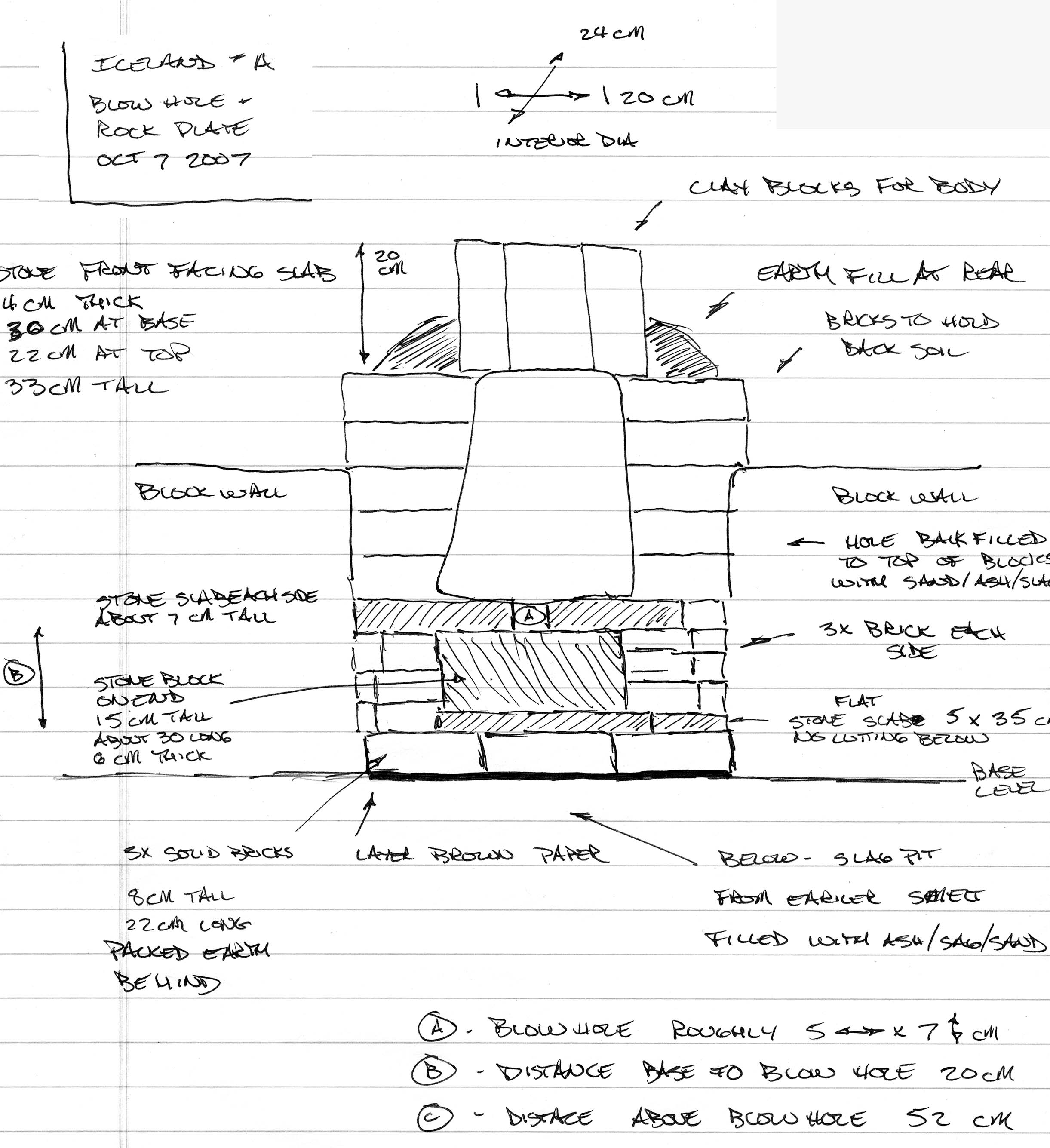
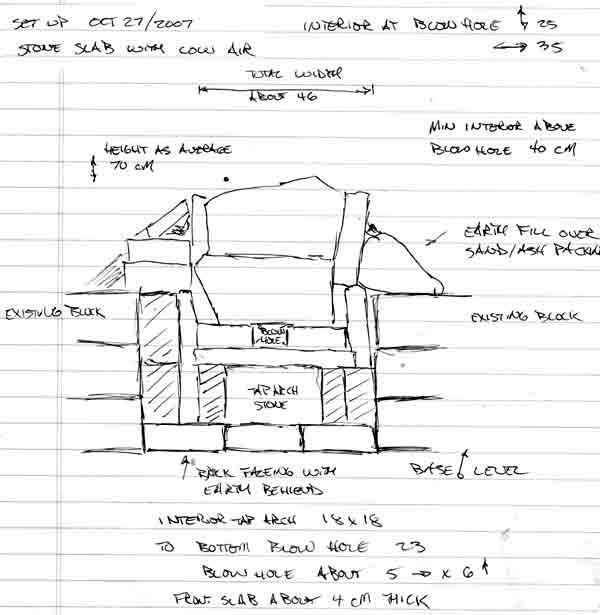
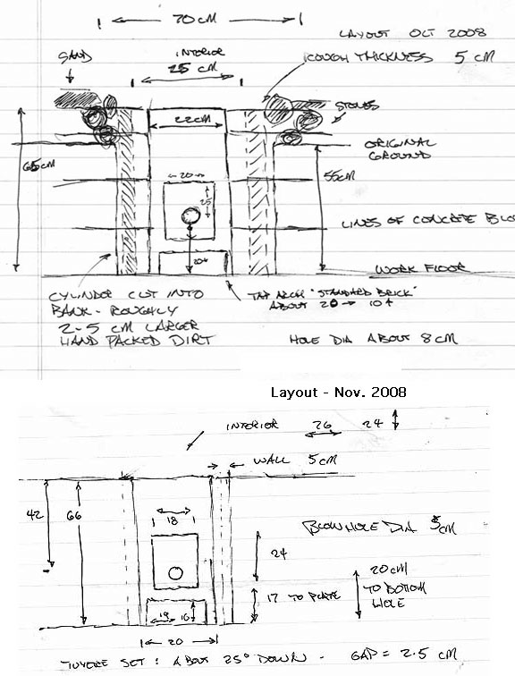
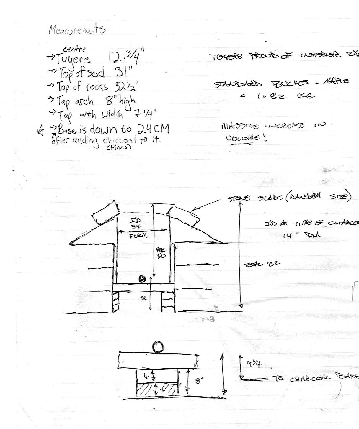
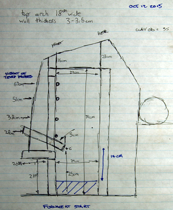
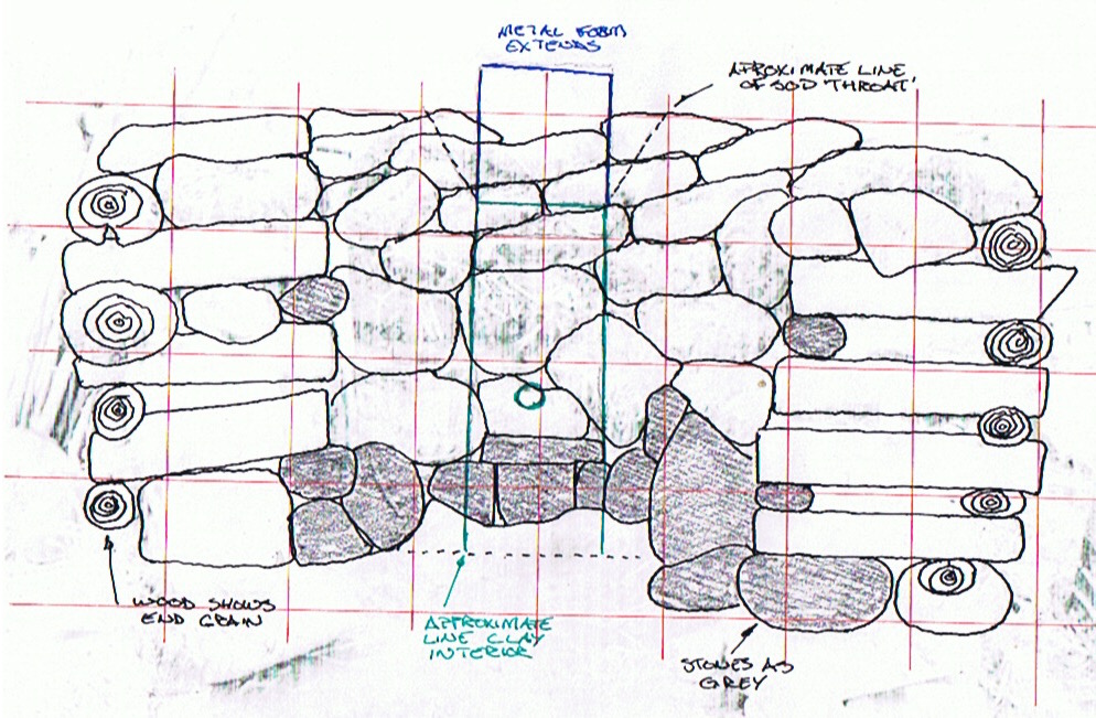